
A multimeter is the most useful tool in electronics and the one most likely to hurt you — not because it is dangerous in itself, but because one wiring mistake turns it into a deliberate short circuit across whatever you are measuring.

This guide covers how to use a multimeter properly, and it puts the safety material first. Most beginner guides leave it out entirely, which is why so many people learn it the expensive way.
Know Your Multimeter’s Jacks Before the Dial

- COM — common. The black lead lives here permanently.
- VΩ (sometimes VΩmA) — voltage, resistance, continuity, diode, capacitance, frequency. The red lead lives here almost all the time.
- mA / µA — small current measurements.
- 10A or 20A — large current. On many budget meters this jack is not fused at all. Check your manual before you rely on it.
The critical point: the jacks set the meter’s input impedance, and the dial sets its function. You need both correct. Getting the jacks wrong is what causes the accident below; getting the dial wrong — an ohmmeter across live mains, say — is its own hazard.
The Mistake That Causes an Arc Flash
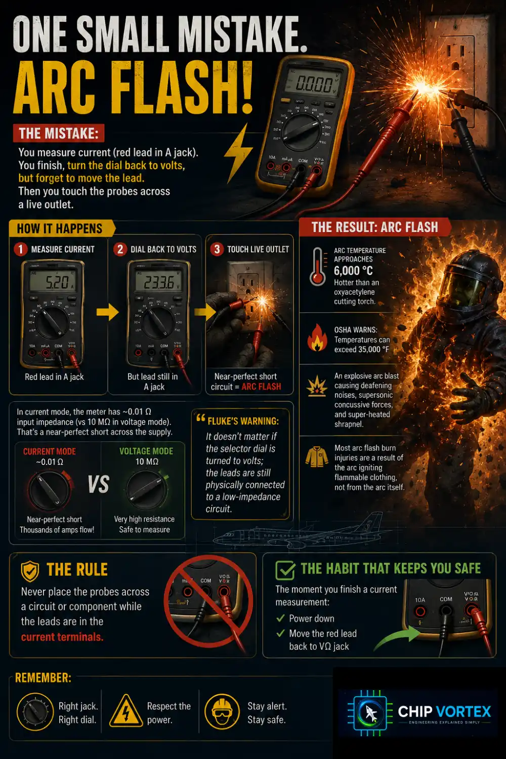
You measure current, which requires the red lead in the A jack. You finish, move the dial back to volts, and forget to move the lead. Then you touch the probes across a live outlet.
In current mode the meter is built to have almost no resistance, because it must not disturb the circuit it is measuring. Fluke gives the input impedance of a 10 A terminal as about 0.01 Ω, against 10 MΩ on the voltage terminals — a billion to one. Connect that across a supply and you have placed a near-perfect short circuit across it. How much current flows is set by the supply, not by the meter, and at a domestic panel or a vehicle battery it is thousands of amps.
Fluke’s warning is the sentence to memorise: “It doesn’t matter if the selector dial is turned to volts; the leads are still physically connected to a low-impedance circuit.”
The result is an arc flash. Fluke describes the arc as approaching 6,000 °C — hotter than an oxyacetylene cutting torch. OSHA notes arc flash temperatures can “exceed 35,000 °F,” with “an explosive arc blast resulting in deafening noises, supersonic concussive forces, and super-heated shrapnel,” and adds a detail worth absorbing: “Most arc flash burn injuries are a result of the arc igniting flammable clothing and not from the arc itself.”
The rule, stated positively: never place the probes across a circuit or component while the leads are in the current terminals. And the habit that enforces it — the moment you finish a current measurement, power down and move the red lead back to VΩ.
Check your own fuse
A decent meter protects its current inputs with high-rupture-capacity fuses. These are sand-filled: the sand absorbs the shock energy of the vaporising element, and the heat fuses it to glass. Fluke specifies minimum interrupt ratings of 10,000 A and 17,000 A; in an 87V the fuses are 0.440 A / 1000 V and 11 A / 1000 V.
Replacing one with a glass fuse from a drawer removes that protection completely — no sand, low interrupting rating, and the fuse body itself becomes the arc path. Fluke’s phrase for the wrong fuse is “a thermal hand grenade.”
Test yours before you trust it: with the meter on continuity, probe from the COM jack to the A jack, then to the mA jack. No beep means a blown fuse. A meter with a blown or incorrect current fuse is unsafe until it is properly repaired.
CAT Ratings: The Number That Actually Matters
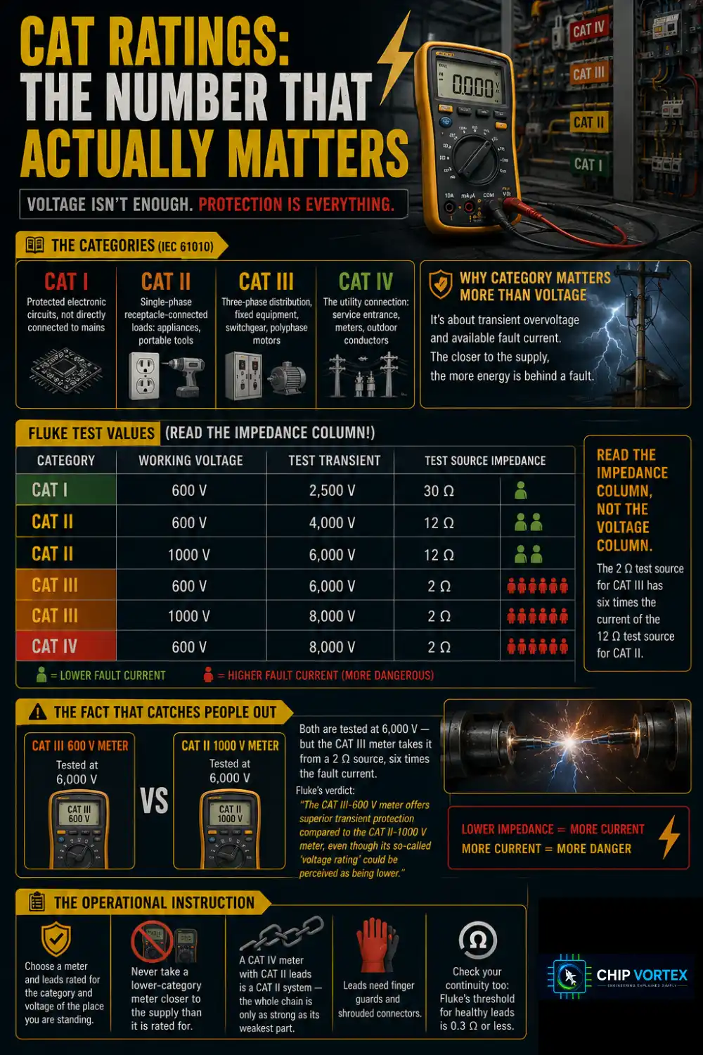
Under IEC 61010 a meter carries a measurement category as well as a voltage:
- CAT I — protected electronic circuits, not directly connected to mains
- CAT II — single-phase receptacle-connected loads: appliances, portable tools
- CAT III — three-phase distribution, fixed equipment, switchgear, polyphase motors
- CAT IV — the utility connection: service entrance, meters, outdoor conductors
The category matters more than the voltage because of transient overvoltage and available fault current. The closer to the supply, the more energy is behind a fault. Fluke’s published test values (this is Fluke’s table, not the complete IEC set):
| Category | Working voltage | Test transient | Test source impedance |
|---|---|---|---|
| CAT I | 600 V | 2,500 V | 30 Ω |
| CAT II | 600 V | 4,000 V | 12 Ω |
| CAT II | 1000 V | 6,000 V | 12 Ω |
| CAT III | 600 V | 6,000 V | 2 Ω |
| CAT III | 1000 V | 8,000 V | 2 Ω |
| CAT IV | 600 V | 8,000 V | 2 Ω |
Read the impedance column, not the voltage column. Fluke: “the 2 Ω test source for CAT III has six times the current of the 12 Ω test source for CAT II.”
Which gives the fact that catches people out. A CAT III 600 V meter and a CAT II 1000 V meter are both tested at 6,000 V — but the CAT III meter takes it from a 2 Ω source, six times the fault current. Fluke’s verdict: “The CAT III-600 V meter offers superior transient protection compared to the CAT II-1000 V meter, even though its so-called ‘voltage rating’ could be perceived as being lower.”
The operational instruction: choose a meter and leads rated for the category and voltage of the place you are standing, and never take a lower-category meter closer to the supply than it is rated for. A CAT IV meter with CAT II leads is a CAT II system — the whole chain, probe tips included, rates to its weakest part. Leads need finger guards and shrouded connectors; check their continuity too, where Fluke’s threshold for healthy leads is 0.3 Ω or less.
How to Measure Voltage With a Multimeter
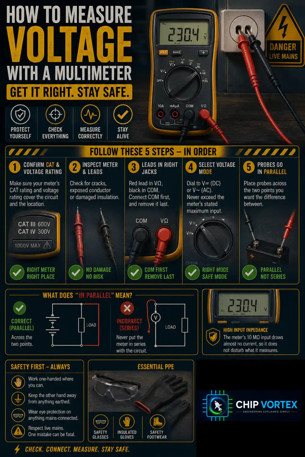
This is where a beginner actually touches live mains, so the checks come first.
- Confirm the meter’s CAT rating and voltage rating cover the circuit and the location.
- Inspect the meter and leads for cracks, exposed conductor or damaged insulation.
- Red lead in VΩ, black in COM. Connect COM first, and remove it last.
- Dial to V⎓ (DC) or V∼ (AC). Never exceed the meter’s stated maximum input.
- Probes go in parallel — across the two points you want the difference between.
Work one-handed where you can, keep the other hand away from anything earthed, and wear eye protection on anything mains-connected. The meter’s 10 MΩ input draws almost no current, so it does not disturb what it measures.
How to Measure Current — the One That Is Different
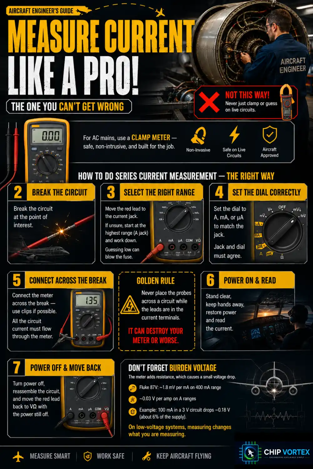
First, consider not doing it this way. For AC mains current the correct answer for most people is a clamp meter, which reads current through the insulation without breaking into the circuit at all. Series current measurement means inserting yourself into a live circuit, and on mains that is a job for someone who already knows what they are doing.
If a series measurement is genuinely the right tool — typically low-voltage DC bench and automotive work — the procedure is:
- Turn the power off, and prove it is off with the meter before touching conductors. On anything beyond a bench supply, lock out and tag out.
- Break the circuit at the point of interest.
- Move the red lead to the current jack. If you are unsure of the magnitude, start at the highest range — the A jack — and work down. Guessing low puts fault current through a lower-rated fuse.
- Set the dial to A, mA or µA to match the jack. Jack and dial must agree.
- Connect the meter across the break — preferably with clips rather than handheld probes — so all the circuit’s current flows through it.
- Stand clear, keep hands away, then restore power and read.
- Remove power, reassemble the circuit, and move the red lead back to VΩ with the power still off.
The rule from earlier applies throughout: never place the probes across a circuit while the leads are in the current terminals. Also observe your meter’s open-circuit limit for in-circuit current measurement — 600 V on a Fluke 117, 1000 V on the 80 Series V. Check yours.
Burden voltage
Inserting the meter adds resistance, so it drops a little voltage — its burden voltage. A Fluke 87V drops roughly 1.8 mV per mA on its 400 mA range, and about 0.03 V per amp on the A ranges. Measuring 100 mA in a 3 V circuit costs 0.18 V, about 6% of the supply. On low-voltage microcontroller work this matters: measuring changes what you are measuring.
How to Measure Resistance With a Multimeter
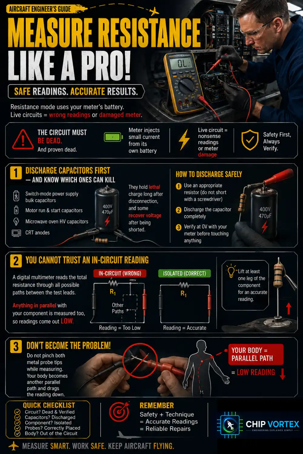
The circuit must be dead, and proven dead. Resistance mode injects a small current from the meter’s own battery; applying it to a live circuit gives nonsense at best and damages the meter at worst.
Discharge capacitors first — and know which ones can kill. Switch-mode power supply bulk capacitors, motor run and start capacitors, microwave oven HV capacitors and CRT anodes hold lethal charge long after disconnection, and some recover voltage after being shorted. Discharge through an appropriate resistor rather than shorting with a screwdriver, then verify at zero volts with the meter before you touch anything. If you are not sure how to discharge a particular capacitor safely, that is the point to stop and find out.
You cannot trust an in-circuit reading. Fluke states why exactly: “The resistance measurement displayed by a digital multimeter is the total resistance through all possible paths between the test lead probes.” Anything in parallel with your component is measured too, so readings come out low. Lift at least one leg of the component.
And do not pinch both metal probe tips while measuring — your body becomes another parallel path and drags the reading down.
Continuity and Diode Test
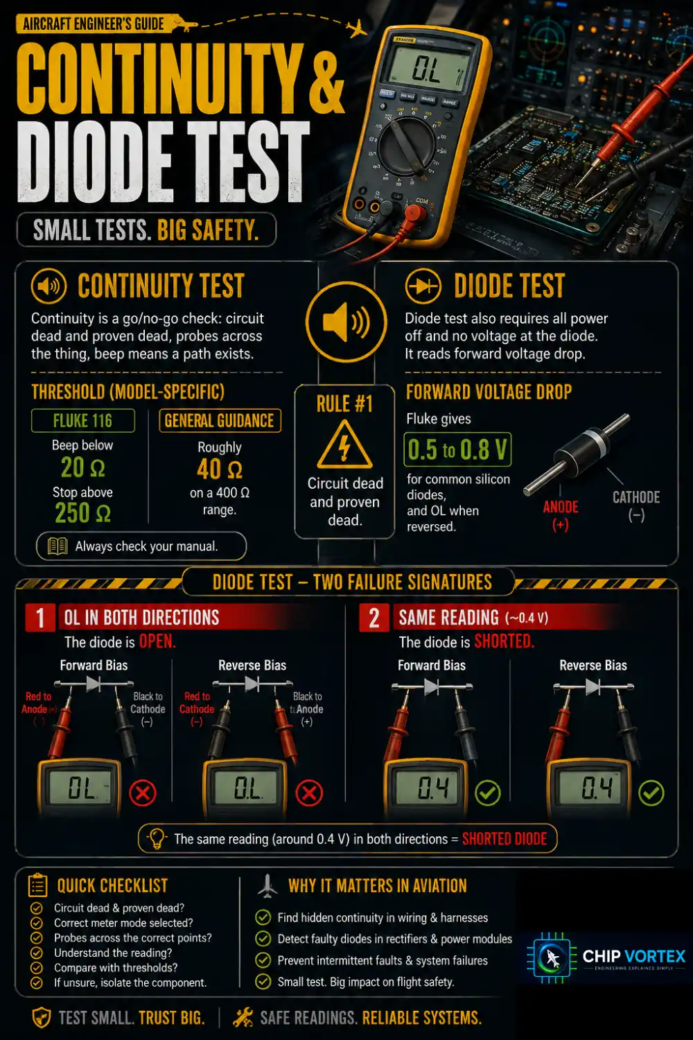
Continuity is a go/no-go check: circuit dead and proven dead, probes across the thing, beep means a path exists. The threshold is model-specific — a Fluke 116 beeps below 20 Ω and stops above 250 Ω, while Fluke’s general guidance mentions roughly 40 Ω on a 400 Ω range. Check your manual.
Diode test also requires all power off and no voltage at the diode. It reads forward voltage drop: Fluke gives 0.5 to 0.8 V for common silicon diodes, and OL when reversed. Two failure signatures:
- OL in both directions — the diode is open.
- The same reading (around 0.4 V) in both directions — the diode is shorted.
Reading the Display
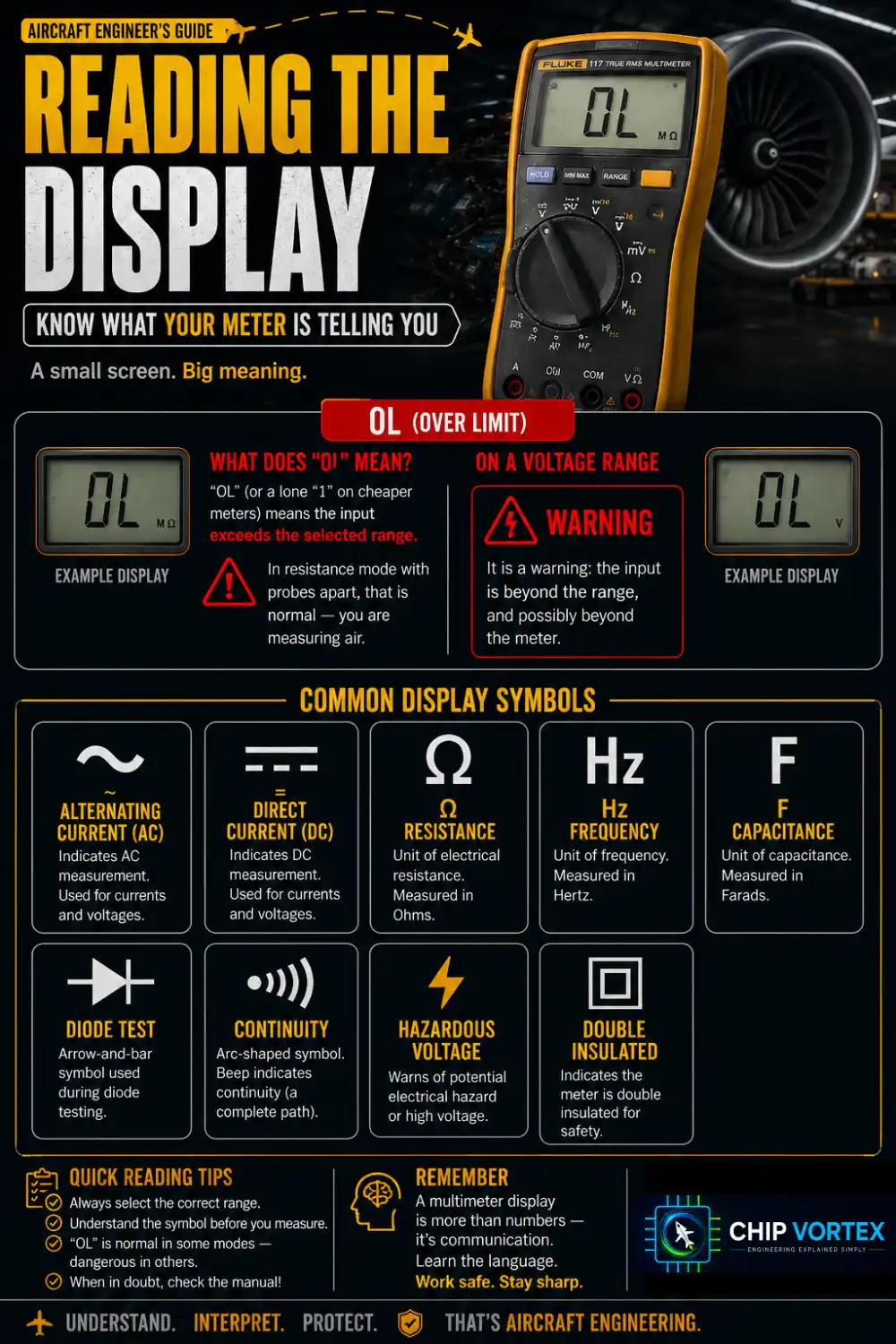
OL (or a lone “1” on cheaper meters) means the input exceeds the selected range. In resistance mode with probes apart that is normal — you are measuring air. On a voltage range it is a warning: the input is beyond the range, and possibly beyond the meter.
Symbols: ∼ alternating current, ⎓ direct current, Ω resistance, Hz frequency, F capacitance, the arrow-and-bar diode symbol, the arc-shaped continuity symbol, ⚡ hazardous voltage, ▣ double insulated.
Ghost Voltages
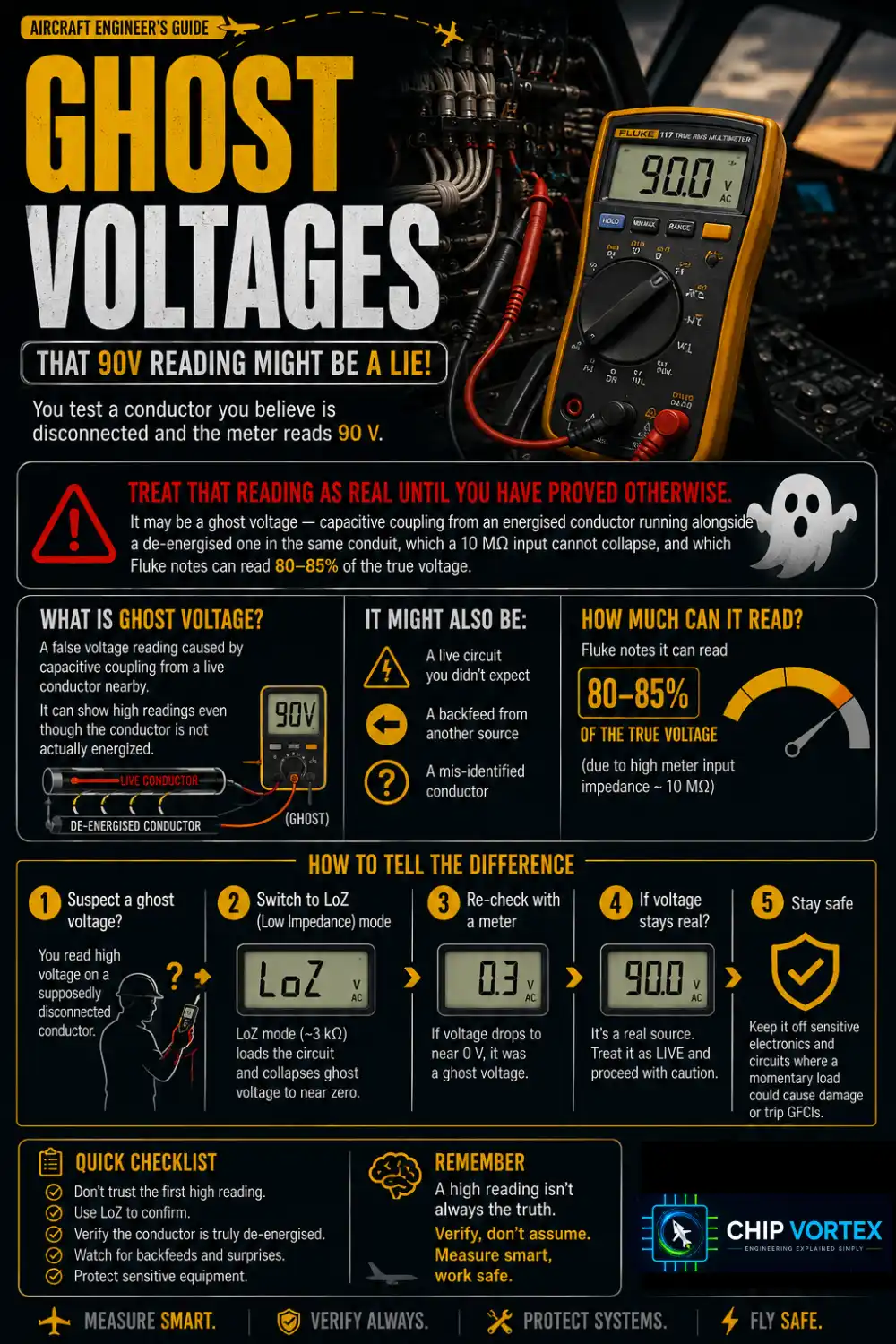
You test a conductor you believe is disconnected and the meter reads 90 V.
Treat that reading as real until you have proved otherwise. It may be a ghost voltage — capacitive coupling from an energised conductor running alongside a de-energised one in the same conduit, which a 10 MΩ input cannot collapse, and which Fluke notes can read 80–85% of the true voltage. It may equally be a live circuit you did not expect, a backfeed, or a mis-identified conductor.
The way to tell them apart is a LoZ (low impedance) mode, around 3 kΩ, which loads a coupled voltage away to near zero while a real source barely moves. Then re-check with a meter you have proven live–dead–live. Use LoZ only to answer “is this live?”, stay within the meter’s rating, and keep it off sensitive electronics and circuits where a momentary load could cause damage — it can also trip GFCIs.
True RMS
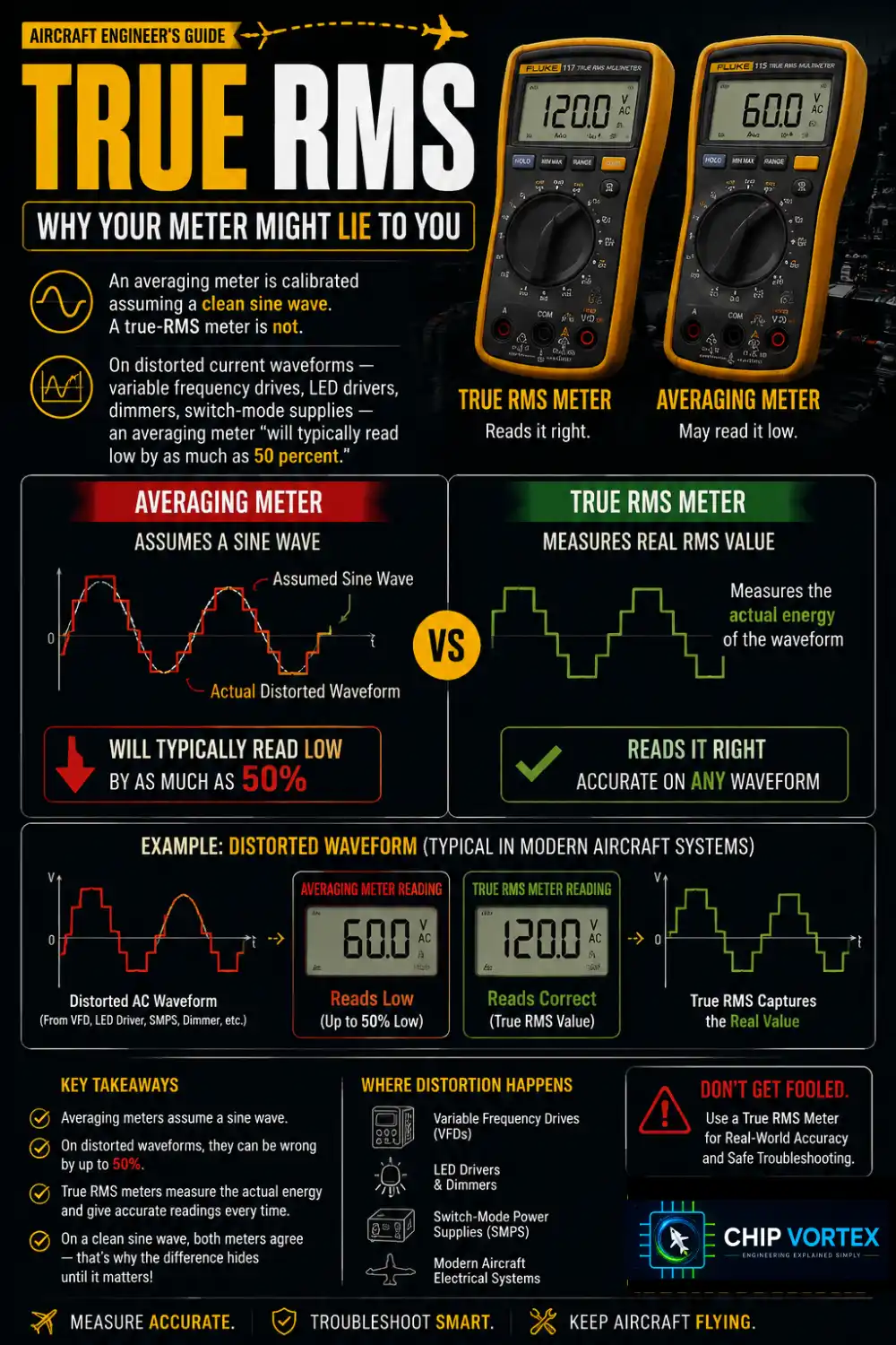
An averaging meter is calibrated assuming a clean sine wave. A true-RMS meter is not.
On distorted current waveforms — variable frequency drives, LED drivers, dimmers, switch-mode supplies — Fluke states an averaging meter “will typically read low by as much as 50 percent.” On a clean sine wave both types agree, which is why the difference stays invisible until it matters.
Live–Dead–Live
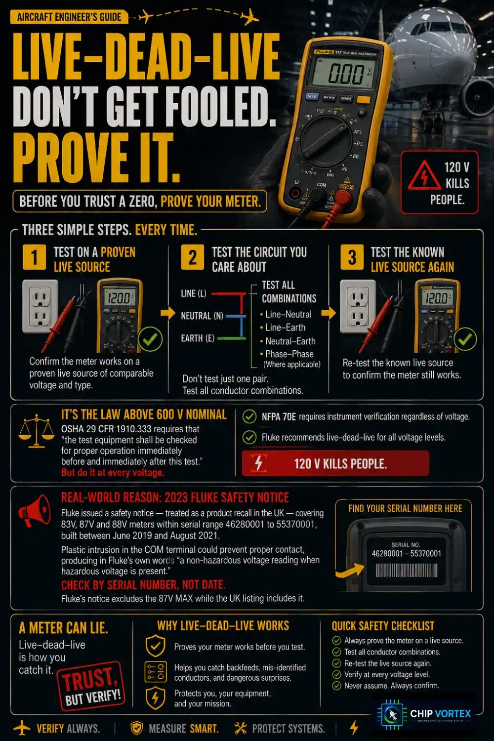
Before you trust a meter that reads zero, prove the meter works.
- Test on a proven live source of comparable voltage and type.
- Test the circuit you care about — all conductor combinations, not one pair: line-neutral, line-earth, neutral-earth, and phase-to-phase where applicable.
- Test the known live source again.
Above 600 V nominal this is law: OSHA 29 CFR 1910.333 requires that “the test equipment shall be checked for proper operation immediately before and immediately after this test.” But do it at every voltage. NFPA 70E requires instrument verification regardless of voltage, and Fluke recommends live–dead–live for all voltage levels. 120 V kills people.
For a concrete reason: in 2023 Fluke issued a safety notice — treated as a product recall in the UK — covering 83V, 87V and 88V meters within serial range 46280001 to 55370001, built between June 2019 and August 2021. Plastic intrusion in the COM terminal could prevent proper contact, producing in Fluke’s own words “a non-hazardous voltage reading when hazardous voltage is present.” Check by serial number rather than date; note that Fluke’s notice excludes the 87V MAX while the UK listing includes it.
A meter can lie. Live–dead–live is how you catch it.
Frequently Asked Questions
Why did my multimeter stop reading current?▾
Almost certainly a blown current fuse — usually from leaving the leads in the A jack and touching a voltage. Replace it only with the manufacturer’s specified high-energy fuse, never a glass one, and do not use the meter until you have.
Is a 1000 V meter safer than a 600 V meter?▾
Not necessarily. A CAT III 600 V meter offers better transient protection than a CAT II 1000 V meter. Read the category before the voltage.
Can I measure mains current by touching the probes across the socket?▾
No — that is the arc flash mistake. Current measurement requires breaking the circuit and putting the meter in series. For mains, use a clamp meter instead.