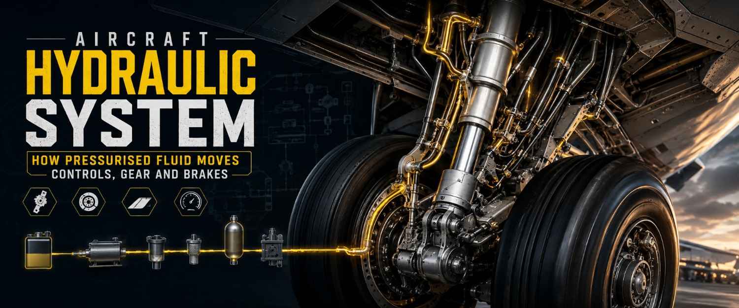
An aircraft hydraulic system transmits force by pumping incompressible fluid at high pressure — commonly 3,000 psi, and 5,000 psi on some newer wide-bodies — through sealed lines to actuators that move flight controls, landing gear, brakes, thrust reversers and nosewheel steering. The core parts are a reservoir, pumps, filters, accumulators, control valves and actuators. Maintenance data sits under ATA Chapter 29.
Build pressure to 3,000 psi, then fail a pump and watch which services you lose first.
[🔧 Try It Yourself: Interactive Aircraft Hydraulic Simulator]
What you just did in ten seconds is the whole subject in miniature. Pressure is generated, stored, distributed and consumed — and the moment supply drops below demand, the system sheds services in a designed order rather than at random. Everything below explains why that order exists and what a technician looks at when it goes wrong.
Why aircraft use fluid instead of cables or electric motors
Fluid multiplies force in a small, flexible package, and unlike a cable run it can be routed around structure without losing mechanical advantage.
Liquid is effectively incompressible, so pressure applied at a pump appears almost instantly at every actuator on that circuit. Increase the piston area and you increase output force for the same pressure — a 3,000 psi supply acting on a 4 square-inch piston delivers roughly 12,000 lb of push.
Cables are lighter for light aircraft and are still used widely there. On larger types the control loads are simply too high for muscle or cable-and-pulley alone, and a hydraulic actuator is far more compact than an electric motor and gearbox of the same output.
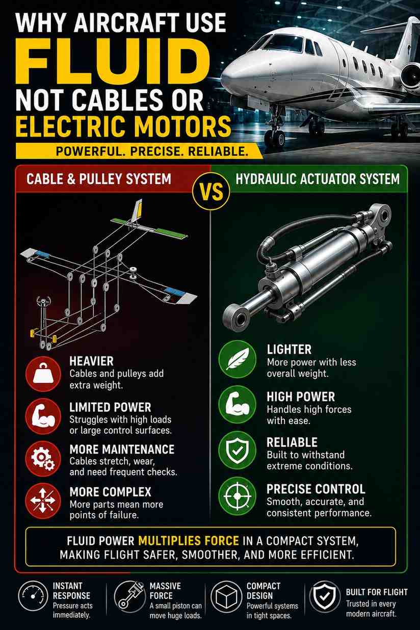
[VERTICAL IMAGE 1000×1500 — side-by-side comparison: a cable-and-pulley control run versus a hydraulic actuator moving the same control surface, with force figures labelled] Alt text: Comparison showing a cable and pulley control run beside a hydraulic actuator, with piston area and output force labelled on the actuator.
The 7 components every hydraulic system has
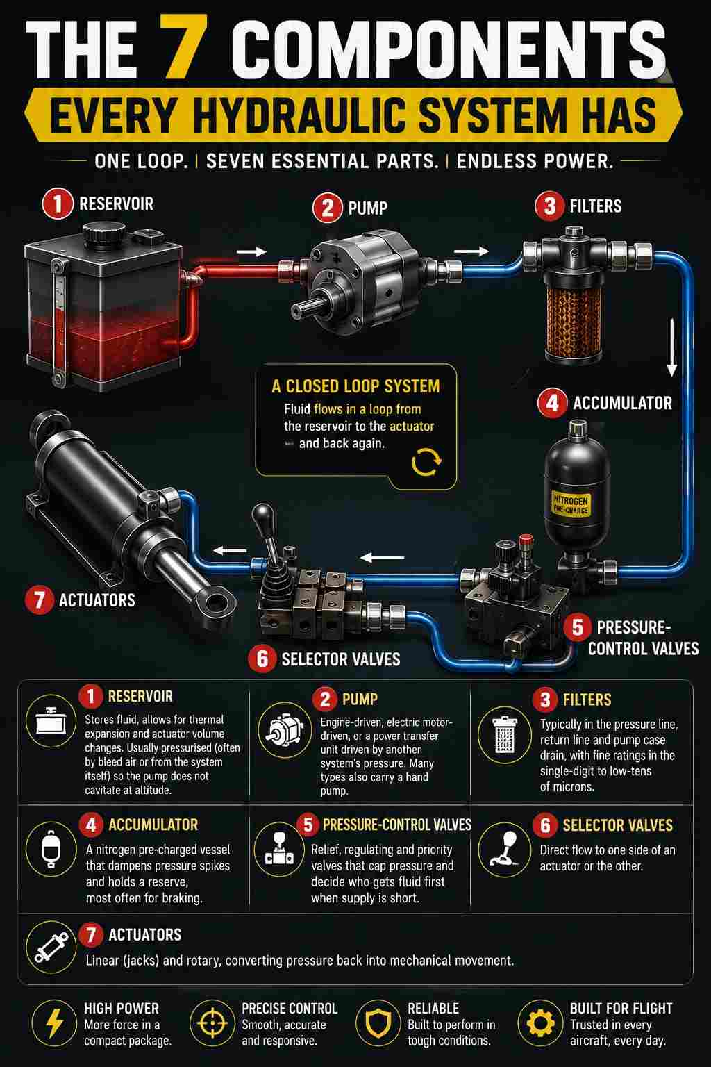
Reservoir, pump, filters, accumulator, pressure-control valves, selector valves and actuators — in that order around the loop.
- Reservoir — stores fluid, allows for thermal expansion and actuator volume changes. Usually pressurised (often by bleed air or from the system itself) so the pump does not cavitate at altitude.
- Pump — engine-driven, electric motor-driven, or a power transfer unit driven by another system’s pressure. Many types also carry a hand pump.
- Filters — typically in the pressure line, return line and pump case drain, with fine ratings in the single-digit to low-tens of microns.
- Accumulator — a nitrogen pre-charged vessel that dampens pressure spikes and holds a reserve, most often for braking.
- Pressure-control valves — relief, regulating and priority valves that cap pressure and decide who gets fluid first when supply is short.
- Selector valves — direct flow to one side of an actuator or the other.
- Actuators — linear (jacks) and rotary, converting pressure back into mechanical movement.
[VERTICAL IMAGE 1000×1500 — numbered closed-loop schematic of a generic hydraulic system, reservoir through to actuator and back] Alt text: Numbered schematic of a closed hydraulic loop showing reservoir, pump, pressure filter, accumulator, control valves, actuator and return line.
Where the pressure comes from when both engines stop
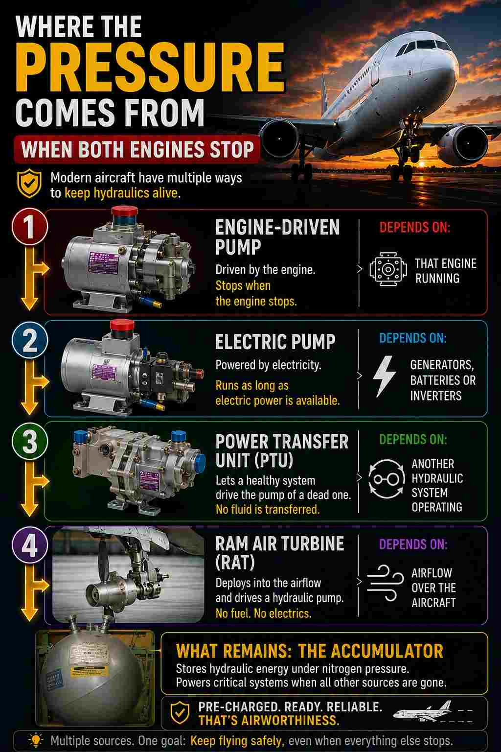
From electrically driven pumps, a power transfer unit, a ram air turbine, or the stored energy already sitting in the accumulator — depending on what the aircraft still has running.
Engine-driven pumps die with their engine, so every transport aircraft carries alternatives. An electric pump can keep a system alive as long as generators or battery-fed inverters supply it. A power transfer unit lets a healthy system drive the pump of a dead one without ever transferring fluid between them.
A ram air turbine deploys into the airstream and, on many designs, drives a hydraulic pump directly — no fuel, no electrics required. What remains after all of that is the accumulator, which is why brake accumulator pre-charge is a genuine airworthiness item, not a formality.
Why one hydraulic system is never enough
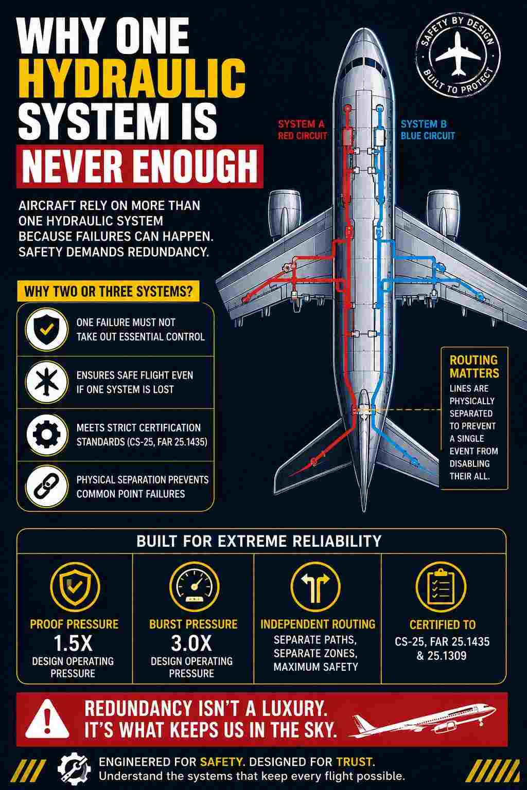
Certification requires that a single failure must not take out essential control, so transport aircraft carry two or three independent systems with physically separated routing.
CS-25 and FAR 25.1435 set the strength floor: hydraulic elements must withstand a proof pressure of 1.5 times and a burst pressure of 3.0 times design operating pressure. Separately, 25.1309 drives the architecture — the number of systems, and how they are split across flight controls.
Routing matters as much as redundancy. Lines for independent systems are deliberately separated so that a tyre burst, an uncontained engine event or a single structural penetration cannot sever all of them at once. The exact split varies by type, so always work from the aircraft’s own system schematic rather than a generic one.
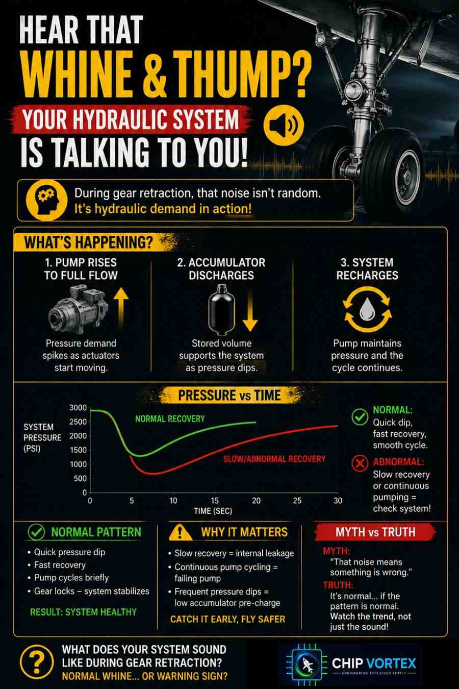
What that whine and thump during gear retraction is telling you
You are hearing pressure demand exceed steady-state supply — the pump rising to full flow, the accumulator discharging, and then the system recharging.
Retracting gear is one of the largest single fluid demands on the aircraft. System pressure dips as the actuators fill, the pump goes to maximum displacement, and the accumulator gives up some of its stored volume. The whine is pump demand; the thump is usually an actuator reaching its stop or a valve sequencing.
The useful part for a technician is the pattern, not the noise itself. A dip that recovers quickly and consistently is normal. A dip that recovers slowly, or a pump that keeps cycling audibly after the gear is up and locked, points at internal leakage, a failing pump, or an accumulator that has lost pre-charge.
Three fluids that must never be mixed — and what happens if they are
Mineral-based, synthetic hydrocarbon and phosphate ester fluids use incompatible seal materials, and cross-contamination swells or dissolves the seals until the system leaks.
| Fluid family | Typical specification | Colour | Compatible seals | Typical application |
|---|---|---|---|---|
| Mineral-based | MIL-PRF-5606 | Red | Nitrile (Buna-N) | Light aircraft, older types |
| Synthetic hydrocarbon | MIL-PRF-83282 / 87257 | Red | Nitrile (Buna-N) | Fire-resistant replacement for 5606 |
| Phosphate ester | Skydrol / HyJet families | Purple (varies by variant) | EPDM / butyl | Most transport category aircraft |
Note the trap in that table: two of the three families are dyed red and are not interchangeable with the purple fluid. Colour alone is not a positive identification — check the specification on the container and the placard at the servicing point.
Phosphate ester fluid is also an aggressive solvent. It strips paint, attacks some plastics, and is an eye and skin irritant, so gloves and goggles are not optional and spills get cleaned immediately rather than at the end of the shift.

[VERTICAL IMAGE 1000×1500 — three labelled fluid containers with their specification, colour and compatible seal material, and a red warning band across the two red fluids] Alt text: Three hydraulic fluid containers labelled with specification, colour and compatible seal material, highlighting that two different families share the same red dye.
Three checks that catch hydraulic problems before they become defects
Inspect the case drain filter, service the reservoir in the configuration the manual specifies, and depressurise fully before breaking any line.
The case drain filter is your pump’s health record. Fine metal particles here mean the pump is wearing internally and will fail later, not now. This is the single most useful early indicator on the system and it is rarely emphasised in coursework.
Reservoir quantity is only meaningful in a defined configuration. Fluid sitting in extended gear or spoiler actuators is fluid that is not in the reservoir. Top up with the aircraft in the wrong configuration and you will overfill — the excess goes overboard the moment those actuators retract.
Residual pressure is the real hazard. A 3,000 psi pinhole jet penetrates skin, and fluid injection injury is a surgical emergency, not a first-aid one. Depressurise the system, discharge the accumulator per the manual, and never search for a leak with your hand.
One further nuance worth knowing: a filter differential-pressure indicator can trip on a cold aircraft simply because cold fluid is more viscous. Note it, but re-check once the system is at normal operating temperature before condemning the element.

[VERTICAL IMAGE 1000×1500 — three-panel vertical layout: case drain filter with metal particles, reservoir sight glass with a configuration note, and a pressure-injection warning icon] Alt text: Three panel image showing a case drain filter containing metal particles, a reservoir sight glass with a servicing configuration note, and a high pressure fluid injection hazard warning.
Quick Reference — Hydraulic Systems
Pressure: commonly 3,000 psi; 5,000 psi on some newer wide-bodies ATA chapter: 29 — Hydraulic Power Strength requirement (CS/FAR 25.1435): proof 1.5× · burst 3.0× design operating pressure
The loop, in order: Reservoir → Pump → Pressure filter → Accumulator → Pressure-control valves → Selector valve → Actuator → Return filter → Reservoir
Power sources, in order of independence:
- Engine-driven pump
- Electric motor pump
- Power transfer unit
- Ram air turbine
- Accumulator stored energy
Fluid families — never mix:
- MIL-PRF-5606 — red — nitrile seals
- MIL-PRF-83282 / 87257 — red — nitrile seals
- Phosphate ester (Skydrol / HyJet) — purple — EPDM / butyl seals
Three field checks:
- Case drain filter → early pump wear
- Reservoir servicing → correct aircraft configuration only
- Depressurise and discharge accumulator → before breaking any line
Accumulator pre-charge: dry nitrogen only — never air or oxygen
Where to go next
Now that pressure generation and distribution make sense, the logical next step is the electrical side that drives the pumps when the engines cannot — start with the A320 electrical system walkthrough and simulator. If you want to see another system where stored energy carries the aircraft through a gap in supply, the APU: what it actually does and when it runs covers the same principle from a different angle. For the cockpit end of the story, reading cockpit instruments: what each indication is really measuring connects the gauges to the hardware behind them. And if you are working through licence modules, the measurement and inspection tools every AME uses guide covers the hands-on skills these inspections depend on.