A gas turbine engine converts fuel into thrust or shaft power by continuously compressing air, burning fuel in it, and expanding the hot gas through a turbine. Almost every airliner, helicopter and business jet flying today is powered by one. For AME and A&P students it is the single most examined powerplant on the syllabus — and once you understand the cycle, every component makes sense.
How a Gas Turbine Engine Works
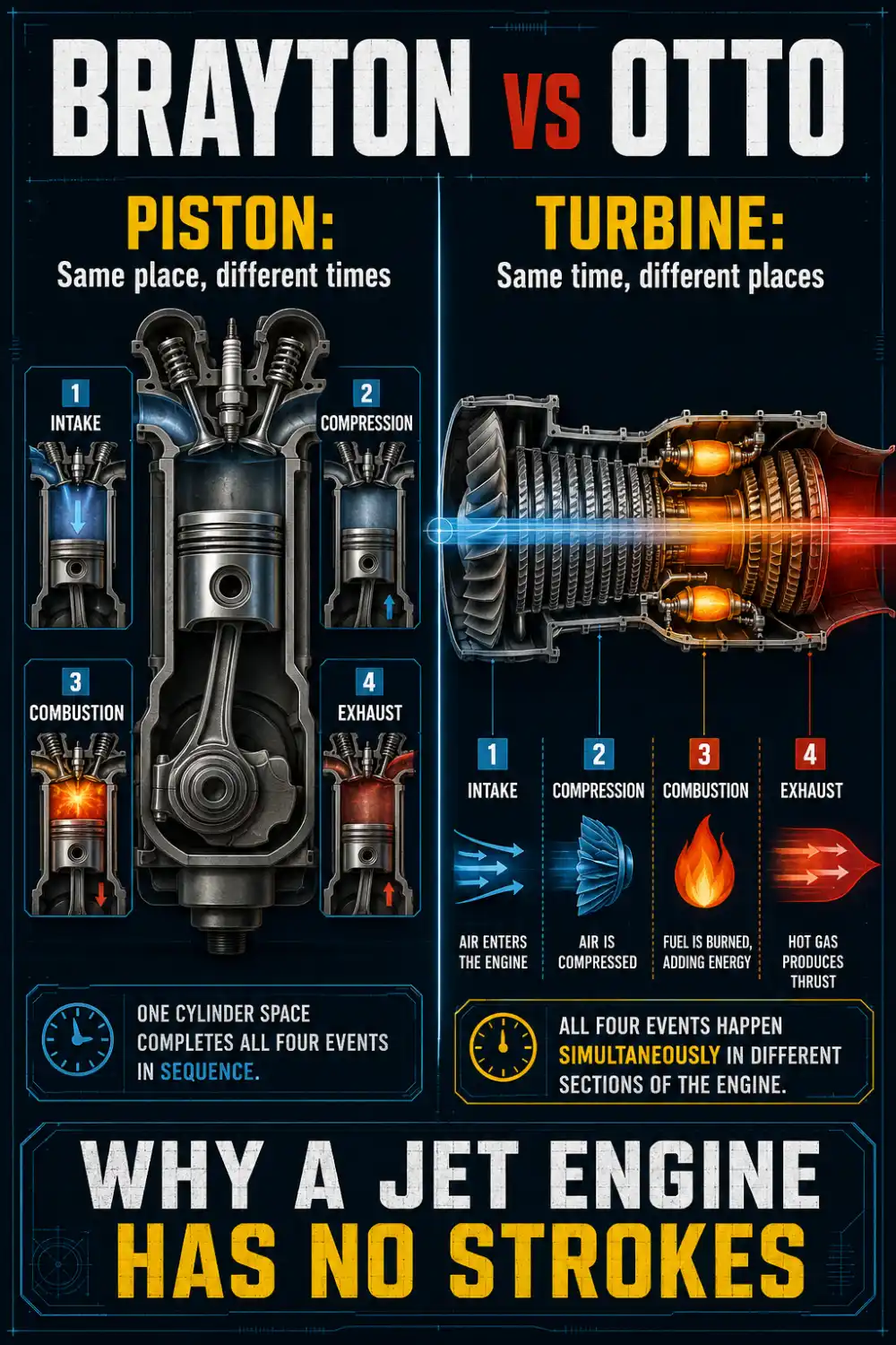
A gas turbine runs on the Brayton cycle. The four events are the same ones you know from a piston engine — intake, compression, combustion, exhaust — but they happen differently:
- Piston engine (Otto cycle): all four events happen in the same place (the cylinder) at different times. Intermittent.
- Gas turbine (Brayton cycle): all four events happen at the same time in different places. Continuous.
That single difference explains why the engine is smooth, has no reciprocating parts, and offers far better power-to-weight. One more distinction for exams: piston combustion happens at roughly constant volume, gas turbine combustion at constant pressure.
Thrust comes from Newton’s third law — accelerate a mass of air rearward and the reaction pushes the aircraft forward. You can do that with a small mass moved very fast (turbojet) or a large mass moved moderately fast (high-bypass turbofan). The second is far more efficient, which is why modern airliners look the way they do.
Gas Turbine Engine Parts: The Five Sections
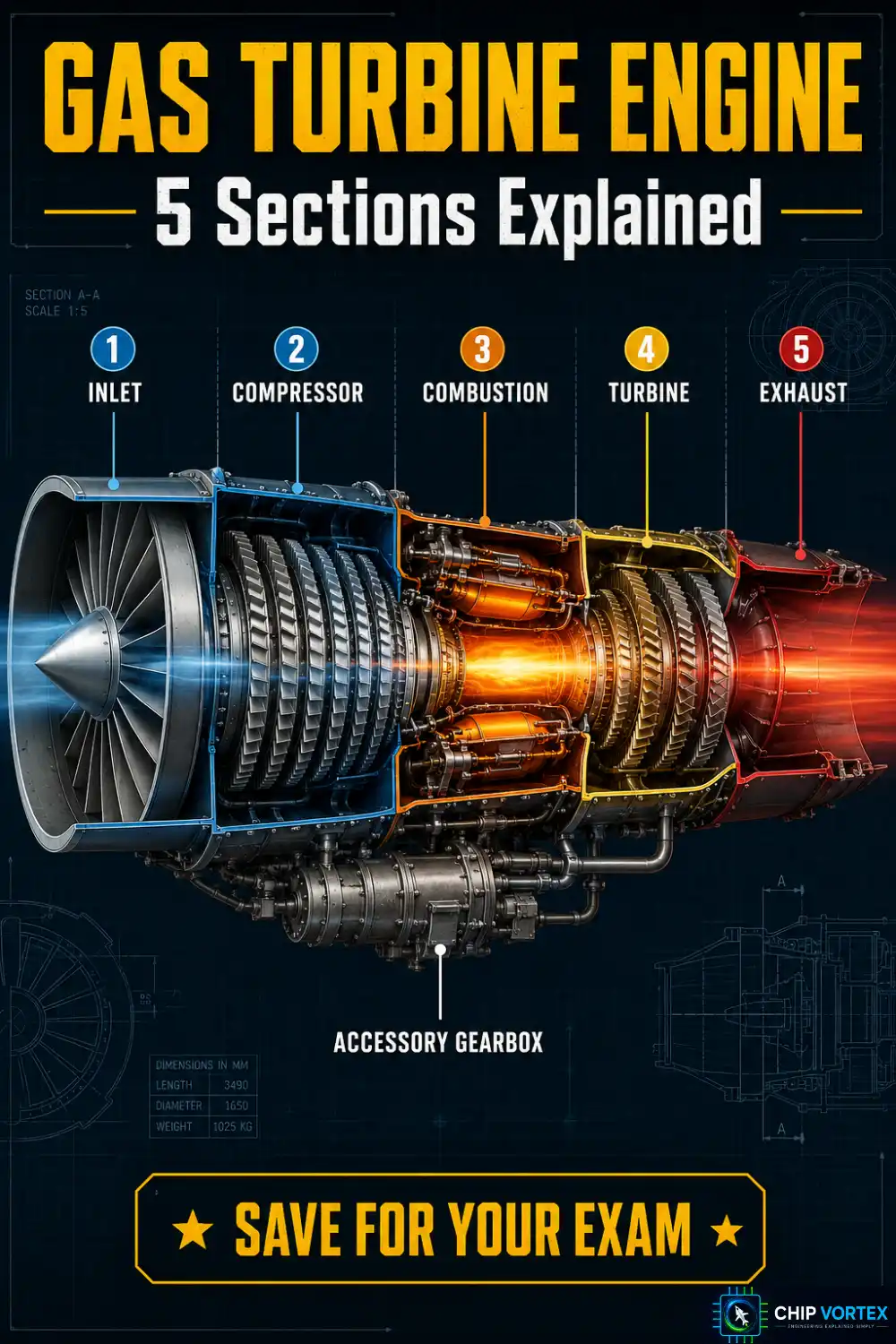
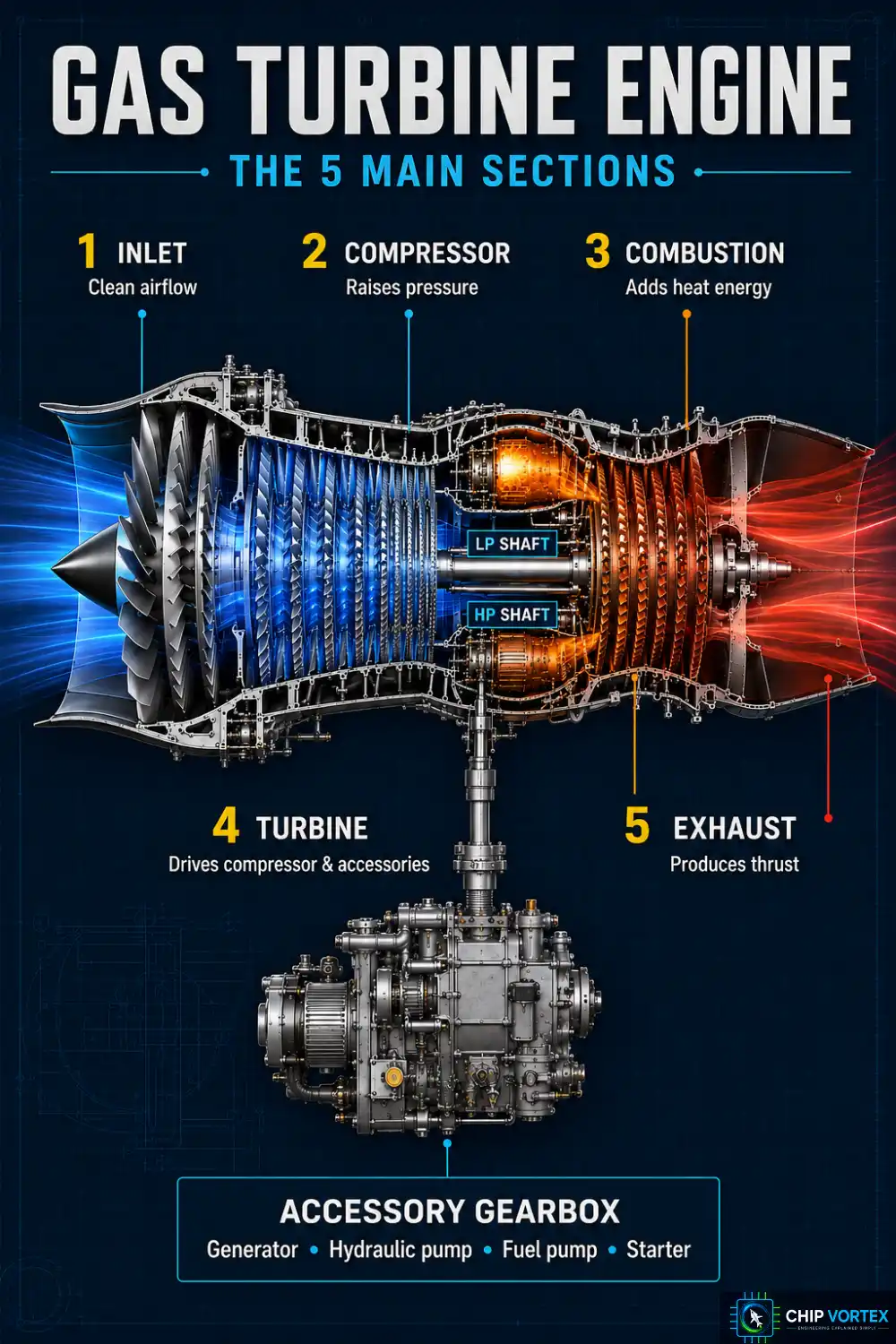
Every gas turbine, from a small turboshaft to a GE9X, is built from the same five sections in the same order — though what the last one is for depends on the engine type:
- Inlet — delivers clean, undisturbed air to the compressor face. In forward flight it also converts velocity into pressure (ram compression); statically on the ground it does the opposite.
- Compressor — raises air pressure and temperature. On a turbojet this absorbs most of the engine’s internal work; on a high-bypass turbofan the fan absorbs more.
- Combustion section — fuel is sprayed into the compressed air and burned continuously at near-constant pressure.
- Turbine — extracts energy from the hot gas to drive the compressor, the fan and the accessories.
- Exhaust — on a turbojet or turbofan it accelerates the remaining gas rearward for thrust. On a turboprop or turboshaft the opposite is true: the design goal is to extract as much energy as possible and leave minimum residual velocity.
One component students forget: the accessory gearbox, mounted on the outside of the engine case and usually driven off the high-pressure spool. It drives the generator, hydraulic pump, fuel pump and starter.
Spools: what N1 and N2 actually mean
The compressor and turbine are split into concentric shafts called spools so each can run at its best speed. On a two-spool direct-drive turbofan, N1 is the fan and low-pressure compressor driven by the low-pressure turbine; N2 is the high-pressure compressor driven by the high-pressure turbine. The speed difference is dramatic — on a CFM LEAP-1A, 100% N1 is 3,856 rpm while 100% N2 is 16,645 rpm. Rolls-Royce Trent engines add a third, intermediate spool. The Pratt & Whitney geared turbofan does it differently again: a reduction gearbox decouples the fan from the LP shaft, so the fan turns slowly while the LP turbine spins fast.
Axial vs Centrifugal Compressors
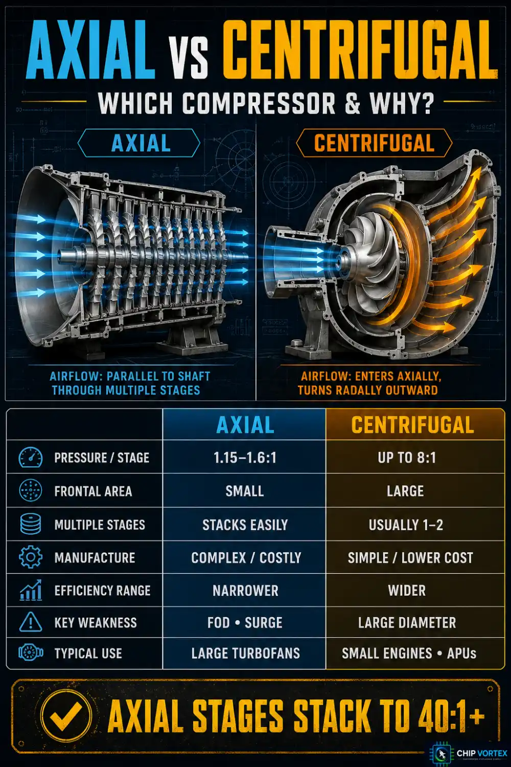
| Centrifugal | Axial | |
|---|---|---|
| Pressure ratio per stage | Up to about 8:1 | ~1.15–1.6:1 |
| Frontal area | Large | Small |
| Manufacture | Simple and cheap | Difficult and expensive |
| Efficiency | Good over a wide speed range | Good over a narrow speed range |
| Weakness | Impractical beyond two stages | FOD, surge, high starting power |
| Typical use | Small engines, APUs | Modern turbofans |
Note what is not on that list: axials are not heavier for the job they do. Per unit of airflow they are lighter — which is why every large engine uses them.
Stack enough axial stages and pressure builds enormously. Modern civil engines run an overall pressure ratio of roughly 40:1 to 55:1 — the GE9X exceeds 60:1. Check the condition quoted, though: OPR at top of climb runs well above the sea-level takeoff figure for the same engine. The WWII Junkers Jumo 004 managed 3.14:1, which shows where seventy years went. Small engines such as the PT6 use an axi-centrifugal layout to get the best of both.
Four Types of Gas Turbine Engine
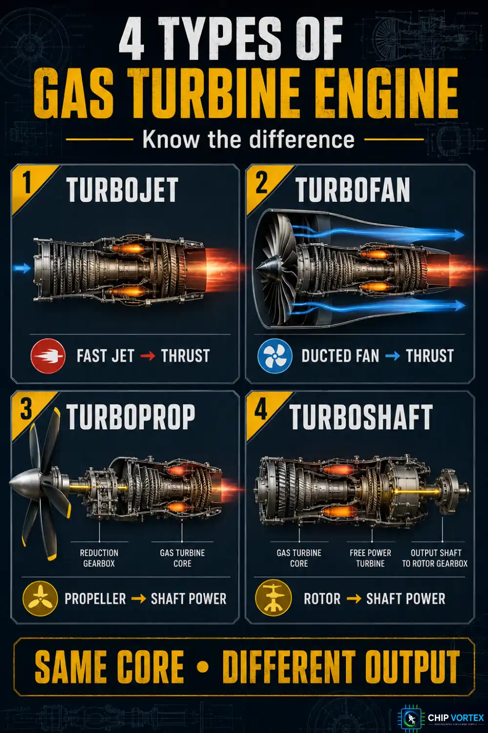
All four share the same core. What differs is how the energy leaves the engine.
| Type | Output | Key feature | Application |
|---|---|---|---|
| Turbojet | Thrust | Energy leaves mainly as a fast jet | Early airliners, supersonic |
| Turbofan | Thrust | Ducted fan bypasses air around the core | Airliners, business jets |
| Turboprop | Shaft power (ESHP) | Propeller driven through a reduction gearbox | Regional and cargo aircraft |
| Turboshaft | Shaft power (shp) | Shaft drives a rotor or other device | Helicopters, APUs, ships |
Two details examiners probe. Turboprops are either free-turbine (a separate power turbine drives the propeller) or fixed-shaft (TPE331, RR 250-B), where the propeller is geared to the compressor shaft. And output is rated in equivalent shaft horsepower, because the residual jet thrust is small but real.
Bypass ratio is the mass of air going around the core divided by the mass going through it. The CFM LEAP-1A runs about 11:1, the Pratt & Whitney GTF around 12.5:1, and the Trent XWB 9.6:1. Military low-bypass turbofans are the opposite extreme — the F135 sits at 0.57:1. On a high-bypass engine the great majority of thrust comes from the fan rather than the core: around 75–80% on the previous CFM56 generation, and higher still at today’s bypass ratios. The core has become, in effect, a gas generator whose job is to turn the fan.
How Turbine Blades Survive Temperatures That Should Melt Them
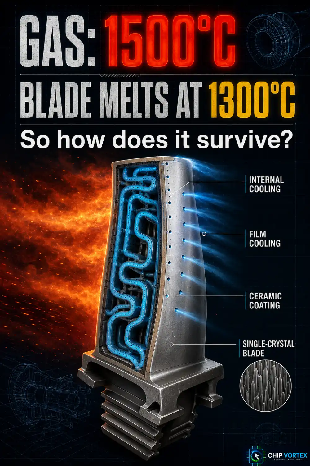
This is the most counter-intuitive fact in the whole engine. Turbine entry temperature is of the order of 1,500 °C, reaching 1,700 °C in the most advanced engines. The nickel superalloy the blades are made from begins to melt around 1,300–1,400 °C. The blades are running in gas hotter than their own melting point.
Four technologies make that survivable:
- Internal cooling passages — high-pressure compressor bleed air, itself several hundred degrees hot, is circulated through channels inside each blade. Modern engines divert 20–25% of HP compressor mass flow to turbine cooling.
- Film cooling — that air exits through tiny surface holes and forms an insulating blanket over the aerofoil.
- Thermal barrier coatings — a ceramic layer of yttria-stabilised zirconia, typically 100–400 microns thick, worth roughly 170 °C on its own.
- Single-crystal casting — each blade is grown as one crystal, removing the grain boundaries where creep failure begins.
In one published example the stack works out at gas around 1,400 °C, ceramic coating surface at 1,100 °C, and the metal underneath at about 930 °C. That gap is what an entire industry of materials science buys you.
Frequently Asked Questions
What is the correct order when starting a gas turbine engine?▾
Starter first, then ignition, then fuel. Airflow must be established through the engine before the mixture is lit, or you risk a hot start. The starter keeps assisting well past self-sustaining speed, then cuts out automatically. Exact percentages are type-specific — always use the AMM.
Why do gas turbines use so many compressor stages?▾
Each axial stage only adds 15–60% to the pressure. Reaching a 40:1 overall pressure ratio therefore takes ten or more stages working in series.
What is the difference between a turboprop and a turboshaft?▾
Mechanically they are near-identical. A turboprop drives a propeller through a reduction gearbox and still produces a little residual jet thrust; a turboshaft drives a rotor or other device and its exhaust is designed to produce almost none.
Next in this series: how the aircraft fuel system delivers fuel to the engine.