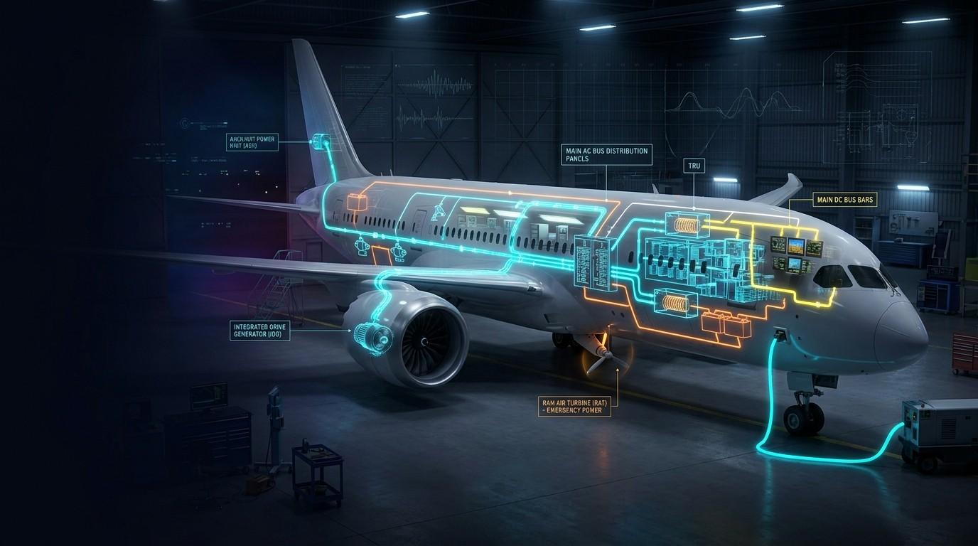
An aircraft electrical system generates, converts, distributes and protects the power that runs every system on board. Transport aircraft typically produce 115 V, 400 Hz three-phase AC from engine-driven generators, convert part of it to 28 V DC through transformer rectifier units, and distribute both through a network of buses, contactors and circuit breakers, with battery and ram air turbine backup.
Do this before you read on: shut down both engine generators and watch which buses stay alive on the battery.
🔧 Try It Yourself: Interactive Aircraft Electrical Simulator
Notice what stayed alive. When both generators dropped, the buses did not all fail together — power was rerouted, non-essential loads were shed, and only the essential bus stayed fed. That priority order is the entire logic of an aircraft electrical system, and everything below explains how it is built.
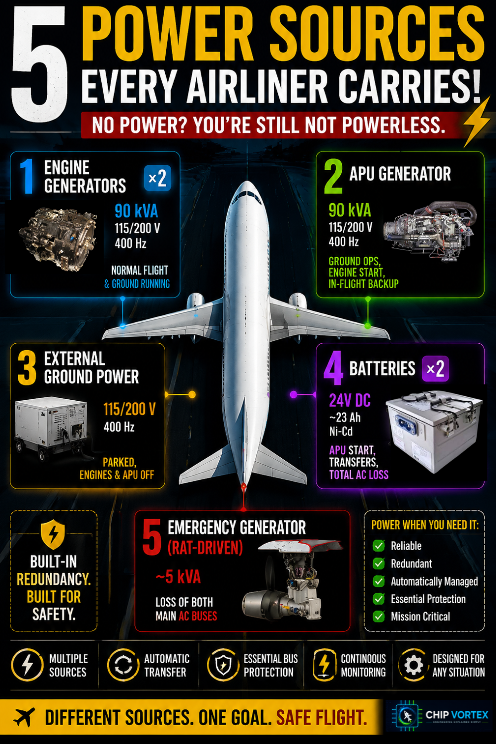
The 5 power sources every airliner carries
Two engine-driven generators, an APU generator, external ground power, batteries, and an emergency generator driven by a ram air turbine.
| Source | Typical A320-family rating | When it supplies the aircraft |
|---|---|---|
| Engine-driven generator (IDG) ×2 | 90 kVA, 115/200 V, 400 Hz | Normal flight and ground running |
| APU generator | 90 kVA, 115/200 V, 400 Hz | Ground ops, engine start, in-flight backup |
| External ground power | 115/200 V, 400 Hz from cart or pit | Parked, engines and APU off |
| Batteries ×2 | 24 V nominal, commonly 23 Ah Ni-Cd | APU start, transfers, total AC loss |
| Emergency generator (RAT-driven) | ~5 kVA | Loss of both main AC buses |
Ratings above are A320-family examples. They vary by type, variant and modification standard — always confirm against the aircraft’s AMM rather than a generic figure.
Priority is not identical across manufacturers. Engine generators always outrank everything else, but whether external power or the APU generator wins below that depends on type and on how the panel is selected. Check the FCOM for the aircraft in front of you.
Field note: the IDG disconnect push-button is not a reset switch. Operate it only with the engine running, and only when the procedure calls for it — once disconnected in flight it stays disconnected, and re-engagement is a ground maintenance action.
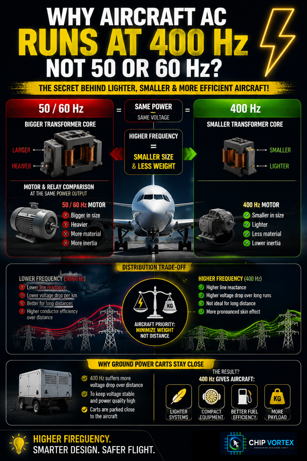
Why aircraft AC runs at 400 Hz and not 50 or 60
Because magnetic components shrink as frequency rises, so a 400 Hz transformer or motor does the same work as a 50/60 Hz unit at a fraction of the weight.
For a given voltage and power, the core cross-section a transformer needs is inversely proportional to frequency. Push from 50 Hz to 400 Hz and that core — plus the iron in every motor and relay — gets dramatically smaller.
The trade-off is distribution. Higher frequency means higher line reactance, more voltage drop over long cable runs and more pronounced skin effect in conductors.
That is why 400 Hz is fine inside an airframe but poor over distance, and why ground power carts sit close to the aircraft instead of feeding it from across the apron.
[VERTICAL IMAGE 1000×1500 — side-by-side scale comparison of a 50 Hz transformer core and a 400 Hz core of equal rating] Alt text: Size comparison between a 50 hertz transformer and a 400 hertz transformer of the same power rating, showing the weight saving that higher frequency allows.
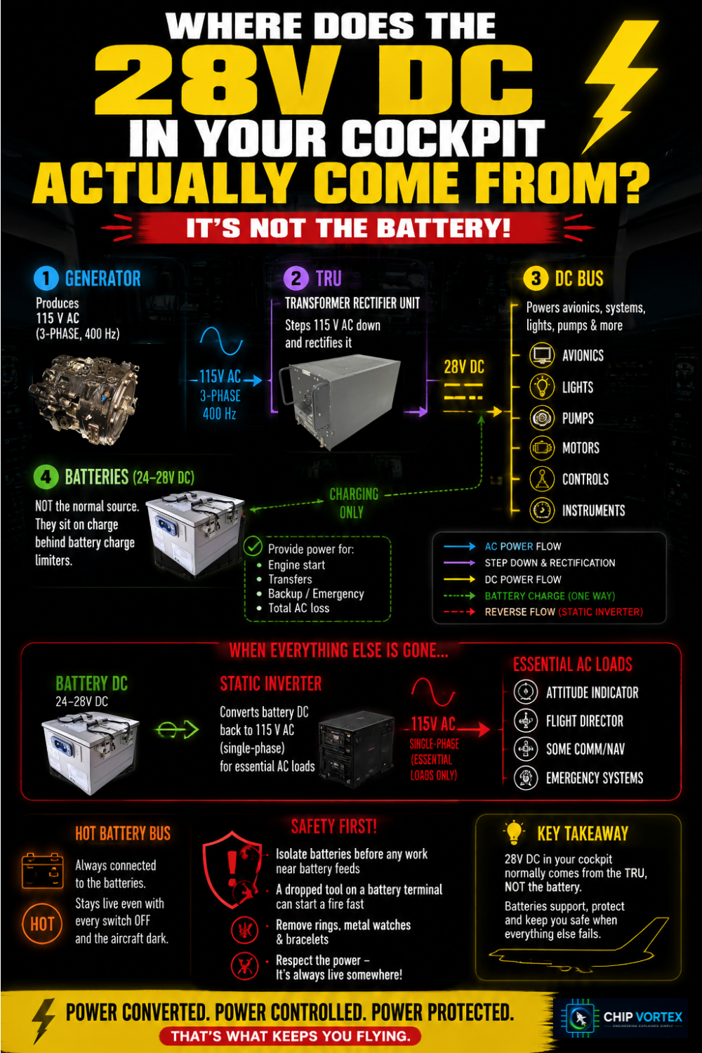
Where the 28 V DC in your cockpit actually comes from
From transformer rectifier units that step 115 V AC down and rectify it to 28 V DC — not from the battery, except when the battery is the only source left.
TRUs feed the DC buses in normal operation, and the batteries sit on charge behind battery charge limiters. Reverse the flow and a static inverter turns battery DC back into single-phase 115 V AC for essential AC loads when no generator is available.
The hot battery buses are the exception to everything. They are permanently connected to the batteries and stay live with every switch off and the aircraft dark.
Safety flag: that is why battery isolation comes before work anywhere near those feeds, and why a dropped spanner across a battery terminal is one of the fastest ways to start a fire in a hangar. Rings and metal watch straps off before you go near the battery compartment.
What really happens when a generator drops offline in flight
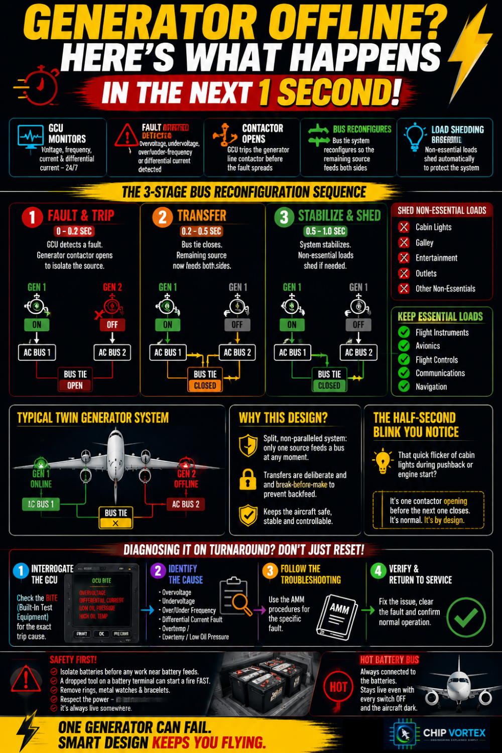
The generator control unit trips the line contactor, the bus tie system reconfigures so the remaining source feeds both sides, and non-essential loads shed automatically.
A GCU is watching for overvoltage, undervoltage, over- and under-frequency and differential current faults. When one of those limits is exceeded it opens the generator line contactor before the fault can propagate into the distribution system.
Most modern twins run a split, non-paralleled system: bus tie contactors make sure only one source feeds a given bus at any moment. Transfers are deliberately break-before-make.
Real world: that half-second blink of the cabin lights during pushback or engine start is exactly this — one contactor opening before the next one closes. It is designed behaviour, not a fault.
Diagnosing it on turnaround: do not simply reset and sign it off. Interrogate the GCU BITE for the trip cause, then follow it. An overvoltage trip points at the generator field or the GCU itself. A disconnect preceded by high oil temperature or low oil pressure points at the drive, not the electrics. A repeated differential fault points at the feeder cable run between generator and bus — inspect it through the pylon, where heat and vibration live.
Why the 787 abandoned 115 V AC for 235 V
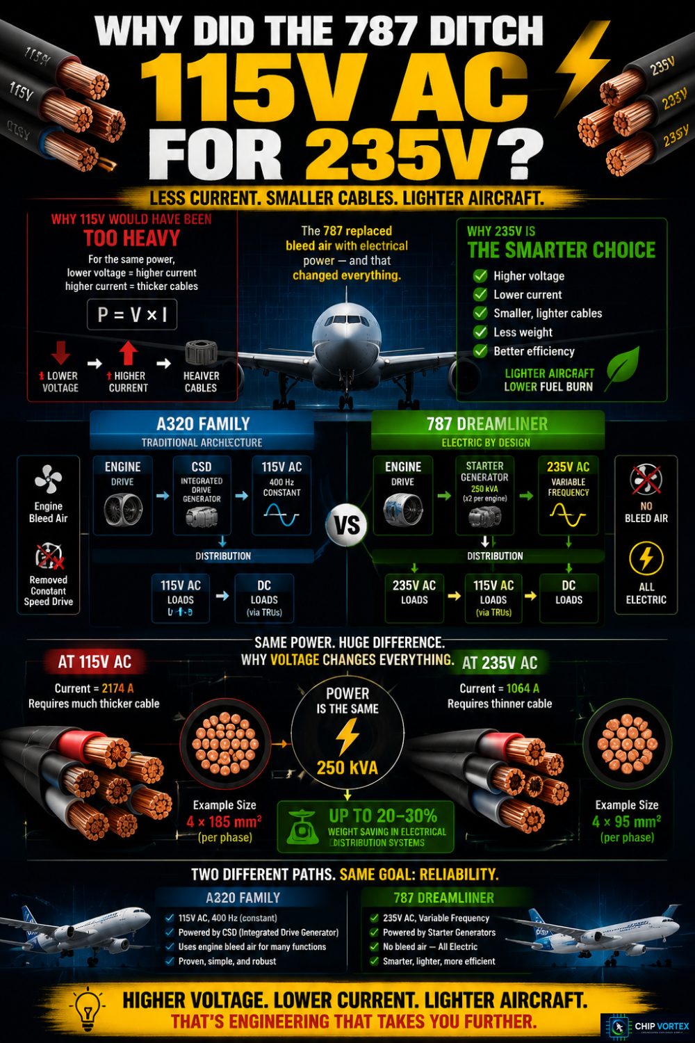
Because it replaced bleed air with electrical power, and moving that much energy at 115 V would have needed impractically heavy feeder cable.
The 787 uses variable-frequency starter generators — two per engine at 250 kVA each, plus two APU generators at 225 kVA — and distributes at 235 V AC variable frequency, converting down to 115 V AC and to DC where loads need it.
The physics is simple: for the same power, doubling voltage halves current, and current is what dictates conductor size. Raise the voltage and the cable, lugs and connectors all get lighter.
The A380 went a different route, keeping 115 V AC but letting frequency vary with engine speed. Both aircraft delete the constant speed drive, and with it one of the more maintenance-hungry items on an older IDG.
| A320 family | 787 | |
|---|---|---|
| Main AC | 115 V, 400 Hz constant | 235 V, variable frequency |
| Drive | Integrated drive generator (CSD) | Direct-drive starter generator |
| Bleed air | Engine bleed | No bleed — electric |
The 3 faults behind most electrical snags in the hangar
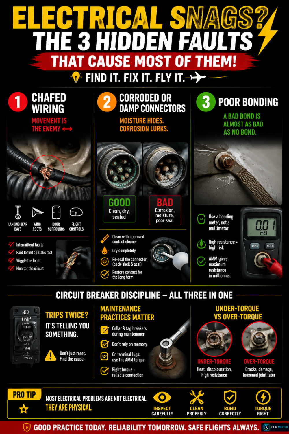
Chafed wiring, corroded or damp connectors, and poor bonding — usually in that order.
1. Chafe at points of relative movement. Landing gear bays, wing roots, door surrounds, flight control areas. Intermittents rarely appear on a static continuity check, so monitor the circuit and wiggle the loom through its range of movement.
2. Moisture and corrosion in connectors. Belly and gear bay connectors take the worst of it. Green or white deposits and a soft back-shell seal mean the fix is clean, dry and re-seal — not a quick de-mate and re-mate that restores contact for two sectors.
3. Bonding that measures fine and isn’t. Use a bonding meter, not a multimeter. A multimeter’s test current is far too low to expose a joint hanging on a few strands; the AMM gives a maximum resistance in milliohms for a reason.
Circuit breaker discipline sits over all three. A CB that trips twice is telling you something, and the answer is not a third reset. Collar and tag breakers during maintenance rather than trusting memory. On terminal lugs, use the AMM torque value: under-torque gives a hot joint that shows up later as discolouration and a smell, over-torque cracks the terminal outright.
Quick reference: aircraft electrical system at a glance
Standard voltages
- 115/200 V AC, 400 Hz, three-phase — main distribution
- 28 V DC — avionics, controls, lighting
- 26 V AC — some instruments and sensors
Source priority (general rule)
- Engine-driven generators
- External power or APU generator (order is type-specific)
- Batteries via static inverter and DC essential bus
- RAT-driven emergency generator
Conversion hardware
- TRU: 115 V AC → 28 V DC
- Static inverter: battery DC → 115 V AC single phase
- Battery charge limiter: controls and monitors charging
Failure logic
- GCU trips on over/undervoltage, over/underfrequency, differential fault
- Bus tie contactors reconfigure, break-before-make
- Non-essential loads shed, essential bus protected
- On the A320, RAT extension is automatic when both main AC buses are lost above roughly 100 kt
Three faults to check first Chafe → connector corrosion → bonding resistance
Where to go next
Run the simulator again now that the architecture makes sense — the load shedding sequence reads completely differently the second time.
- A320 Electrical System Simulator — repeat the generator failure with the bus logic in mind
- APU System Simulator — see where that 90 kVA generator sits in the wider system
- Aircraft Cockpit Instruments Explained — what the 26 V AC and 28 V DC feeds are actually powering
- How Aircraft Hydraulic Systems Work — the electric pumps that draw from these buses
Written by a trainee B1.1 aircraft maintenance engineer — Module 3 (Electrical Fundamentals) and Module 11 background, with hands-on time in the hangar. Figures quoted are typical values for the types named; always work to the AMM and FCOM for the specific aircraft and modification standard in front of you.