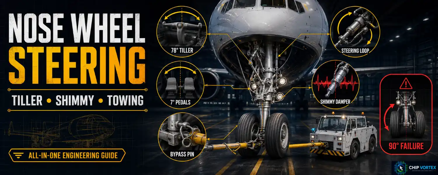
Nose wheel steering is what turns an aircraft on the ground below the speed at which the rudder becomes effective. On a light aircraft it can be a spring and a pushrod. On an airliner it is a closed-loop hydraulic servo — and when it fails, the aircraft can end up landing with its nose wheels turned sideways.
Light Aircraft: Direct Linkage and Free-Castoring
Two arrangements dominate small aircraft.
Direct linkage. Push-pull tubes connect pedal horns on the lower strut cylinder, so moving the rudder pedals physically rotates the nose wheel. The Cessna 172 POH gives the classic figures: the nosewheel is steerable through 10° each side of centre, with differential braking increasing the turning arc to 30° each side.
Free-castoring. The Cirrus SR20/SR22, Diamond DA40 and Grumman AA-5 have no steering connection at all — the nose wheel simply swivels (through a full 180° on the AA-5), and the aircraft is steered entirely by differential braking and rudder. Cirrus’s own manual describes relying on “aerodynamic forces and differential braking,” using rudder deflection and intermittent toe taps. These types depend wholly on brakes and tyre condition for directional control, which makes the maintenance points later in this article more consequential, not less.
The FAA’s advice applies to both: stop with the nose wheel straight ahead, to relieve side load on the strut.
Transport Aircraft: Tiller vs Rudder Pedals
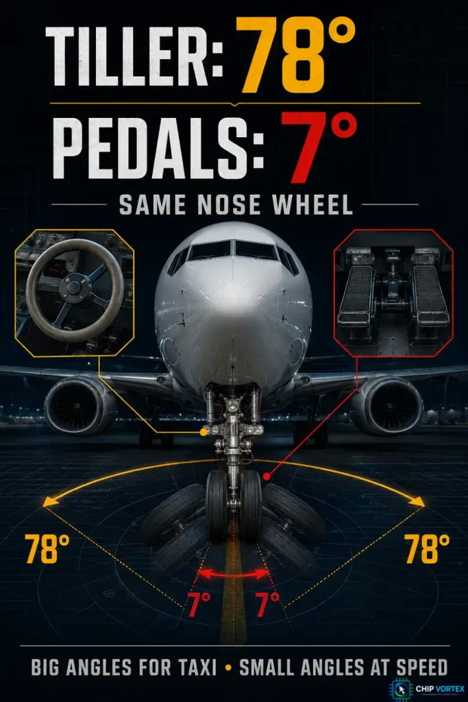
Large aircraft split steering authority between two controls, and the asymmetry is bigger than students expect. Two sets of figures from official investigation reports:
| Aircraft | Tiller | Rudder pedals |
|---|---|---|
| Boeing 737-800 | 78° each way | 7° each way |
| Embraer EMB-145 | 71° | 5° (76° combined) |
The 737 figures come from an AAIB bulletin and a TSB Canada report independently; the EMB-145 figures from an NTSB systems group factual report. On the A320 the corresponding pedal figure is ±6° below 40 knots — and note the qualifier, because pedal steering authority is speed-scheduled rather than fixed. The figures above are maxima too.
One behaviour worth knowing: on the 737, tiller input overrides rudder pedal input, and there is no mechanical lock preventing tiller use at higher speed. That is a design fact, not a permission — the Boeing FCTM instruction is “do not use the nose wheel steering wheel until reaching taxi speed.” On the A320 the BSCU mathematically adds handwheel and pedal inputs instead of one overriding the other.
Inside the System: The Follow-Up Loop
Hydraulic steering is a closed loop, and if you have read our autopilot article the principle will be familiar — it is exactly the same error-correction idea.
Take the FAA’s generic large-aircraft teaching example. The tiller drives a metering valve through cables. The valve ports fluid to one of two opposed steering actuators. As the gear rotates, gear teeth on the steering spindle drive an orifice rod and scissor links to a follow-up drum, whose cable returns the metering valve to neutral once the commanded angle is reached. A compensator holds around 100 psi in the cylinders at all times, so they also act as dampers.
That is the whole trick. The metering valve is a summing point between what the pilot asked for and what the gear has actually done, and it closes when the two agree. Without it, every steering input would overshoot. (The FAA presents this arrangement for instruction rather than as any specific type — real installations vary.)
On fly-by-wire types the metering valve becomes an electrohydraulic servo valve commanded by a computer — the BSCU on the A320, the Steering Electronic Control Module on the EMB-145 — but the loop is unchanged.
Two ways to apply the torque
Opposed linear actuators either side of the strut act as a push-pull crankshaft mechanism, which means the moment arm — and so the available torque — changes across the steering range. Rack-and-pinion designs give more uniform torque throughout, but demand tight backlash control. And backlash, as the next section explains, is how shimmy starts.
Centring Cams
Inside the shock strut, an upper cam mates into a lower cam recess as the strut extends after lift-off. This centres the nose wheel so the gear retracts straight into the bay. When the strut compresses on landing, the cams disengage, allowing the lower strut to rotate for steering.
The failure case is instructive: if the wheels can rotate off-centre while retracted, the tyres can jam the gear in the wheel well.
Shimmy and the Shimmy Damper
Shimmy is a self-excited oscillation of the nose wheel, arising when the gear’s torsional and lateral bending modes couple through the elastic tyre. Reported frequencies vary widely by gear design — from around 6 Hz up into the tens of hertz. It is not cosmetic. It fatigues the gear and the surrounding structure.
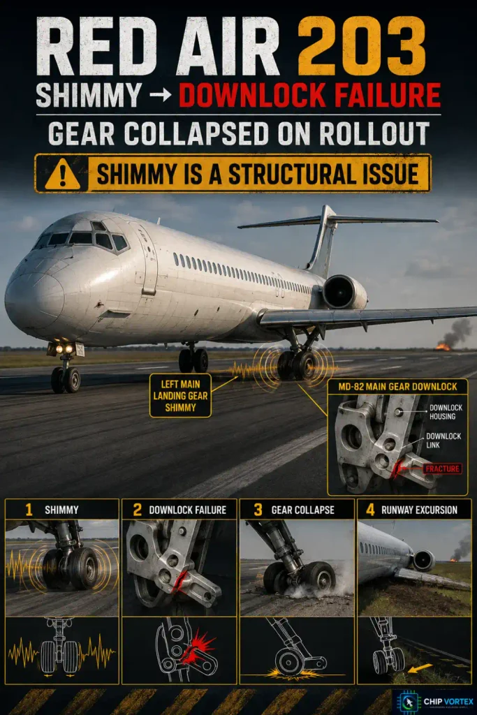
The proof of how serious it gets is RED Air Flight 203 (MD-82, Miami, 21 June 2022). The NTSB probable cause, verbatim from docket DCA22FA132:
“The structural failure of the left main landing gear downlock following ineffective shimmy dampening during the landing roll which caused the collapse of the left main landing gear, resulting in a runway excursion and post-flight fire.”
Two points of precision. That was the left main gear, not the nose gear — which is also a reminder that main gears on some types carry their own dedicated dampers. And the aircraft was substantially damaged, not destroyed: the post-crash fire was a right wing fuel tank fire after striking a glideslope shelter, extinguished by the fire service. Four of the 140 on board sustained minor injuries.
Damper types
- Piston type — as the strut tries to shimmy, fluid is forced through a bleed hole in the piston. Slow steering movement passes freely; rapid oscillation is resisted.
- Vane type — rotating vanes divide the housing into chambers; chamber size can only change as fast as fluid passes the orifice.
- Non-hydraulic (surface effect) — a rubber piston presses against the housing bore. No fluid to service. Lord units are approved for the Cessna 150, 152, 172, 182, 206, 207, 208 and 210.
- On hydraulically steered nose gear, the steering actuators often do the damping themselves — the compensator keeps them pressurised, so no separate damper is fitted. Main gears on some transport types do still carry dedicated dampers, as RED Air 203 demonstrated.
Causes, in the order to check them
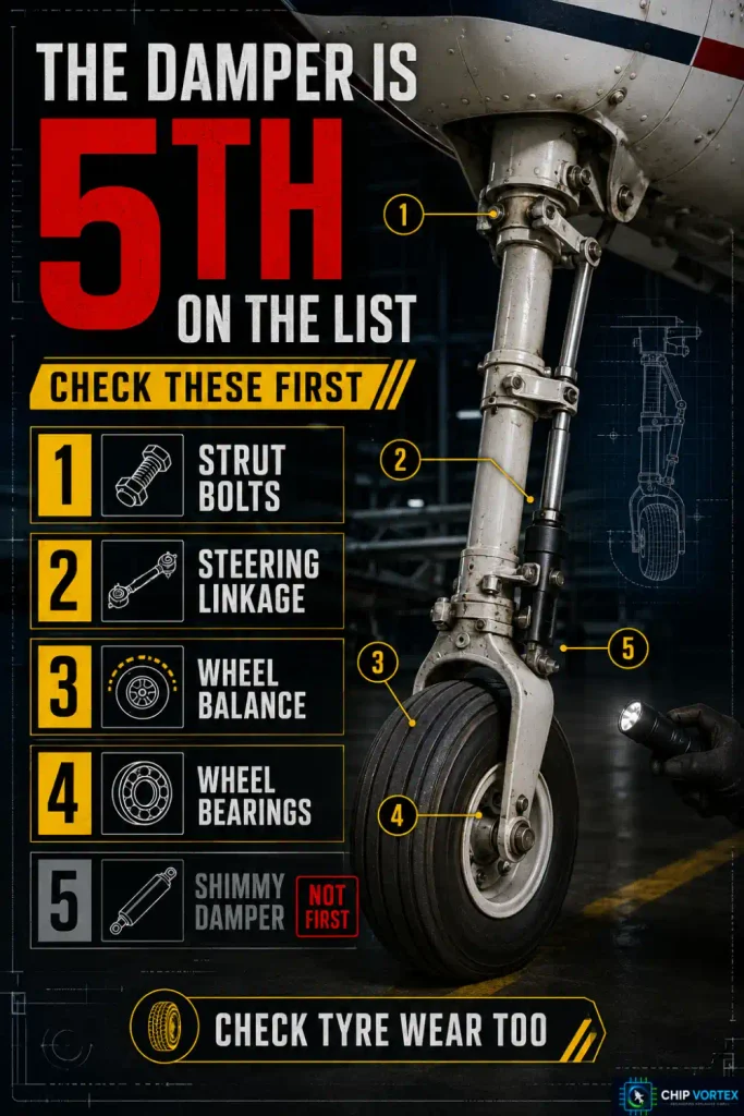
Cessna’s classic list: loose nose strut attachment bolts, worn or loose steering linkage, out-of-balance nose wheel, loose wheel bearings, defective shimmy damper, low fluid in the damper, loose torque links.
Note where the damper sits on that list — fifth. AOPA’s maintenance guidance follows the same instinct: check wheel imbalance and uneven tyre wear first, then the bushings, bolts and rod-end joints, and only then suspect the damper. Condemning the damper first is the classic mistake, and shimming the steering collar to remove residual play generally comes at the end rather than the beginning.
Servicing
Damper fluid level is a routine check — commonly quoted at 50-hour intervals for Cessna singles, though always work to the current maintenance manual rather than a remembered number. Use the fluid the manual specifies; note that MIL-H-5606 is the relevant family, and the old “MIL-H-5606A” revision letter you will see in older text is obsolete. Even a small amount of trapped air compromises damping. Rod-end bearings should have almost undetectable play. One overhaul shop reports that around 90% of dampers it receives have had no routine maintenance at all.
Torque Links
The torque links — the scissors — keep the lower strut from rotating out of alignment with the aircraft’s longitudinal axis, hinged in the centre so the strut can still extend and compress. They are the only torsional restraint between the wheel and the airframe, which is precisely why free play at the apex pin shows up as shimmy.
Towing and the Bypass Pin
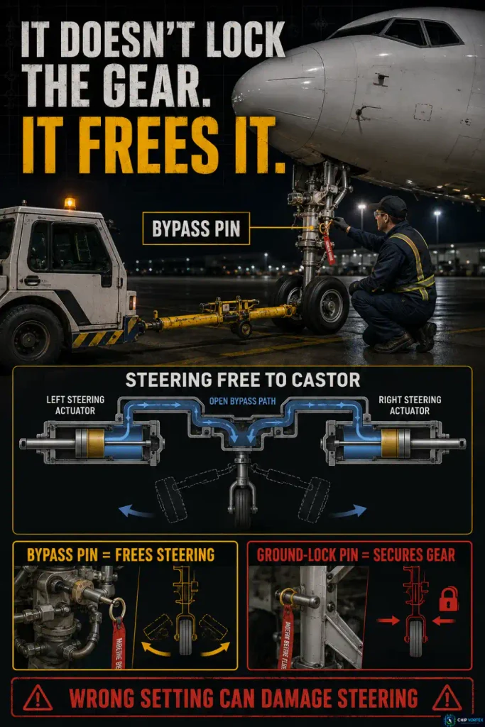
Before an aircraft is towed, the steering must be disconnected. The bypass pin opens a bypass between the two sides of the steering actuators, isolating the hydraulic steering so the nose gear castors freely under the tug’s control.
Get this the right way round. The bypass pin does not lock the nose gear — that is the job of the gear ground-lock pin. It does the opposite: it frees the gear, so the steering system cannot fight the towbar or be damaged by it.
Two documented consequences of getting this wrong:
- An A321 was towed with the towing control lever incorrectly set. When the right engine started, the nose wheel steering system pressurised and was damaged as a result (AAIB, EC-HUI).
- Dassault found that failure to disconnect the nose gear torque link before towing accounted for 22 of 68 towing events analysed — with the Falcon 900EX turn radius limited to 100° when the torque link is not connected. One report describes “a loud pop” from the nose gear after a sharp turn.
Angle limits matter in ordinary taxiing too. FAA SAIB NM-13-25 warns that on the Gulfstream GVI, turning with differential braking “could result in damage to the nose wheel if the nose wheel angle exceeds 84 degrees.”
When Steering Fails: JetBlue 292
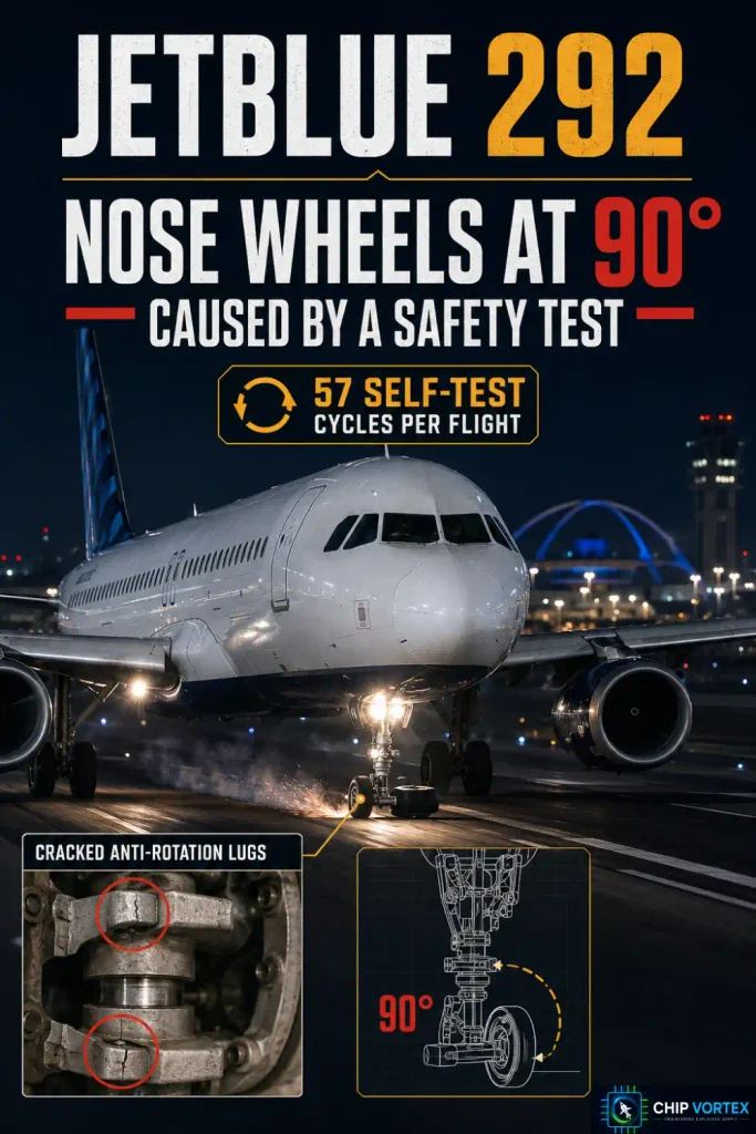
On 21 September 2005, JetBlue Flight 292 — Airbus A320 N536JB — landed at Los Angeles with its nose wheels turned 90° to the direction of travel, live on television.
The NTSB probable cause (LAX05IA312) is unusually elegant, and it indicts a test:
“The fatigue failure of two anti-rotation lugs due to repeated cyclic pre-landing tests, which allowed the nosewheels to deviate from the 0-degree position on landing gear retraction. A contributing factor was the design of the Brake Steering Control Unit (BSCU) system logic, which prevented the nosewheels from centering. Also contributing was the lack of a procedure to attempt to reset the BSCU system under these conditions.”
The mechanism: that BSCU standard ran a pre-landing self-test cycling the nose wheels 2.5° left, centre, 2.5° right, centre — about five seconds per cycle, repeating until main gear touchdown, averaging 57 cycles per flight. Four anti-rotation lugs hold the shock absorber in rotational alignment. Two failed in fatigue and the other two cracked. With the lugs gone the wheels could rotate on retraction, and the BSCU logic then prevented re-centring.
A self-test intended to confirm the system was healthy was fatiguing the component it tested. Later software reduced the cycles to eight, and the following standard eliminated them.
Frequently Asked Questions
How much rudder does it take to hold the centreline?▾
Less than students expect. In an AAIB investigation into a 737 that suffered a nosewheel bearing failure on landing, Boeing’s analysis found that roughly 2–3° of right rudder pedal, increasing to 4° by the time the aircraft stopped, would have kept it on the centreline. Note those are pedal degrees, not rudder surface deflection.
Why is rudder pedal steering authority so small?▾
Because the pedals must remain usable at speed, where a large nose wheel deflection would be uncontrollable. The tiller supplies the large angles at taxi speeds.
Which regulation covers nose wheel steering loads?▾
14 CFR 25.499 for nose-wheel yaw and steering, and 25.509 for towing loads — which explicitly contemplates the gear swivelled 45° during a tow.
Related reading: the aircraft emergency systems guide and the aircraft autopilot system.