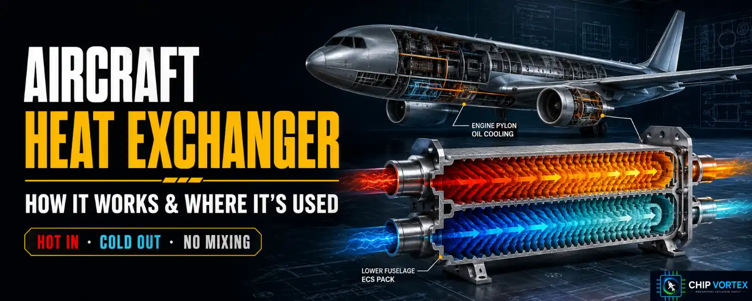
An aircraft heat exchanger moves heat from one fluid to another without ever letting the two mix. That is the whole idea — and it is the reason a modern airliner can cool engine oil, chill cabin air, and stop fuel from icing using nothing more exotic than a metal wall between two flows.
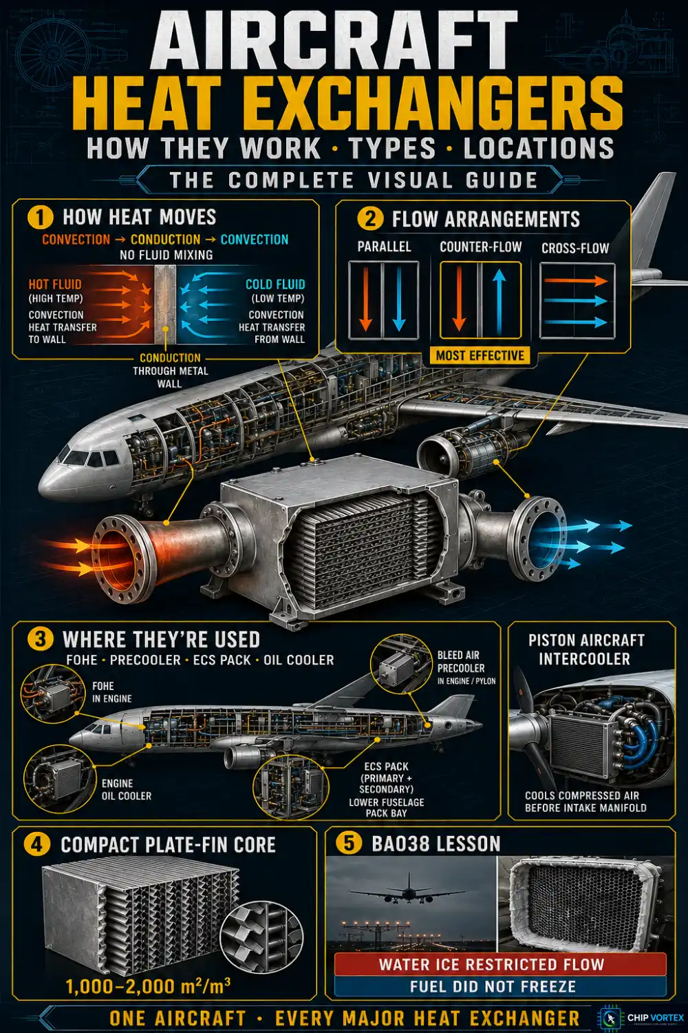
In January 2008 a restricted one brought a Boeing 777 down short of the runway at Heathrow. We will come back to that.
How a Heat Exchanger Works
Three heat transfer steps happen in series:
- Convection from the hot fluid to the dividing wall.
- Conduction through the wall itself.
- Convection from the wall into the cold fluid.
In a recuperative exchanger — the type used almost everywhere on aircraft — the fluids never touch. Performance comes down to raising the overall heat transfer coefficient, increasing the surface area, or increasing the temperature difference between the streams.
There is a fourth constraint that textbooks underplay and aerospace cannot: pressure drop. Every fin you add to gain surface area costs pressure, and on the ram-air side that pressure loss becomes drag. In aircraft installations this is usually what sizes the unit, not the thermal calculation.
Parallel, Counter-Flow and Cross-Flow
The three arrangements are defined by how the two streams are routed relative to each other:
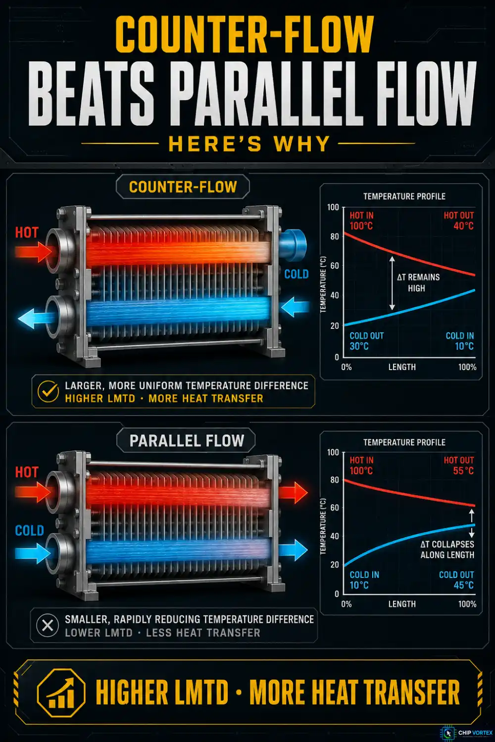
- Parallel (co-current) — both fluids enter at the same end and travel the same way. The temperature difference is huge at the inlet and collapses toward zero at the outlet.
- Counter-flow — the fluids enter at opposite ends and travel in opposite directions.
- Cross-flow — the streams cross, usually at right angles. Real aerospace units are often hybrids.
Counter-flow is the most thermally effective, and the reason matters. It maintains a far more uniform temperature difference along the whole length. In a parallel-flow exchanger the cold fluid outlet can never exceed the hot fluid outlet temperature; in counter-flow, the cold outlet can approach the hot fluid’s inlet temperature. For the same terminal temperatures, counter-flow produces a higher log mean temperature difference (LMTD), and since heat duty follows Q = U × A × LMTD, you get more heat transferred from the same hardware.
That equation is exact only for pure parallel or counter-flow. For the cross-flow hybrids common in aerospace it becomes Q = U × A × F × LMTD, where the correction factor F is always ≤ 1 — and F = 1 is the counter-flow case. Another way of saying counter-flow is the benchmark everything else is measured against.
Types Used in Aircraft
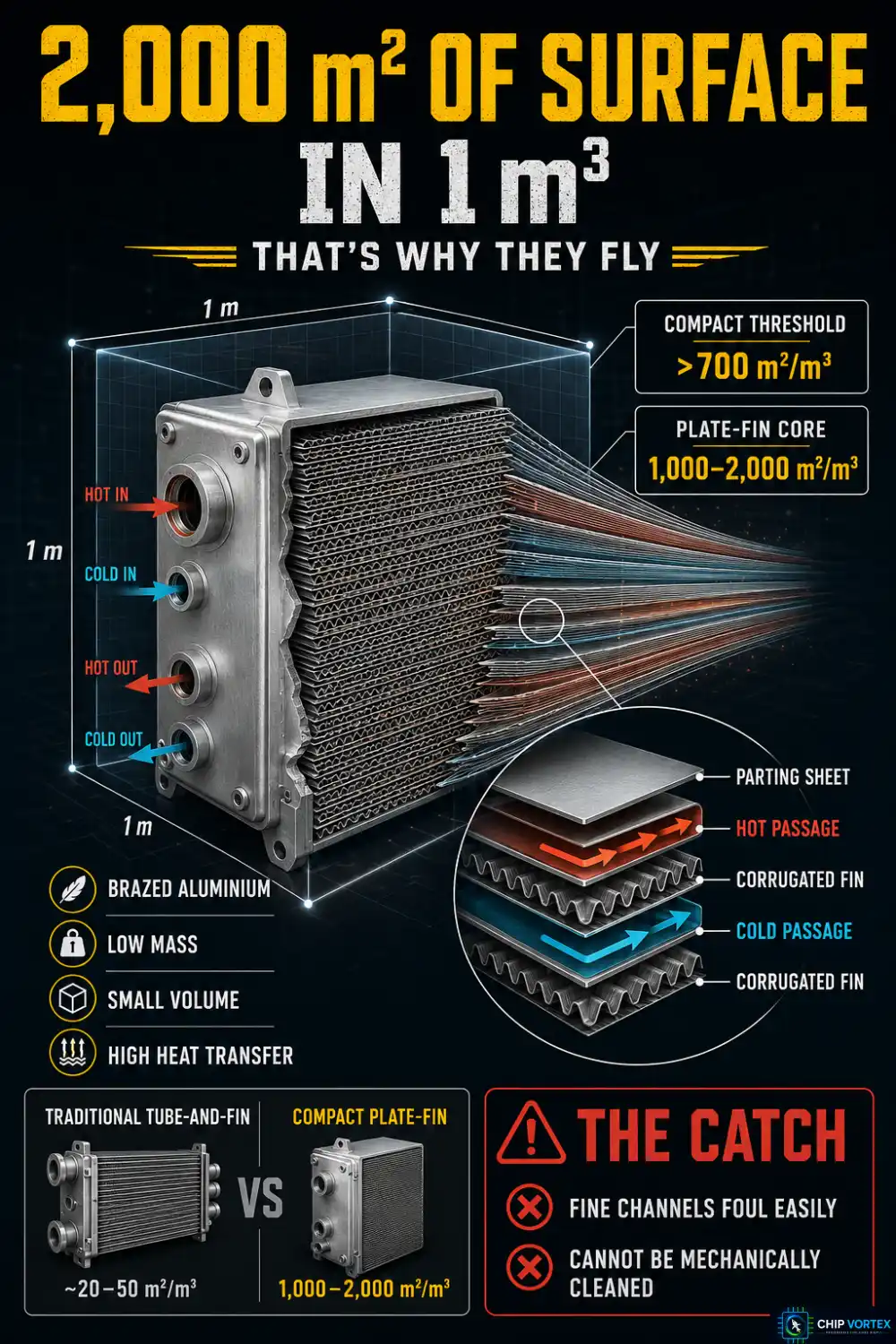
A heat exchanger is called compact when surface area density on at least one side exceeds 700 m²/m³ for gas-to-fluid duties, or 400 m²/m³ for liquid-to-liquid. Brazed plate-fin cores typically run 1,000–2,000 m²/m³ and higher with fine aerospace fin surfaces — which is exactly why they dominate aircraft installations, where every kilogram and every litre is contested.
- Plate-fin — corrugated fin sheets between flat plates, vacuum-brazed into a solid core. Aluminium alloy plate-fin has been used in aircraft since the 1940s. The weakness: the tiny flow channels foul easily and cannot be mechanically cleaned, so chemical cleaning and upstream filtration are the real defences.
- Tubular — bundles of tubes, generally more robust, sometimes with individually replaceable tubes. Shell-and-tube is a subset of this family, alongside double-pipe and spiral-tube; it is common industrially but less so in flight-weight applications.
Materials follow the temperature. Aluminium for ECS and oil duties, stainless steel further up, and Inconel where bleed air arrives genuinely hot.
Where Heat Exchangers Are Used on an Aircraft
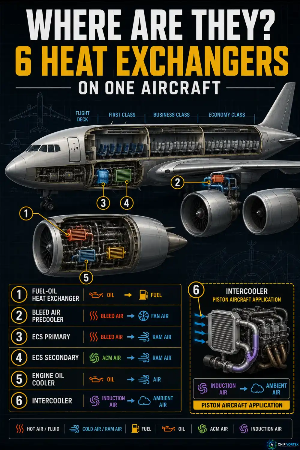
Fuel-oil heat exchanger (FOHE)
Also called a fuel-cooled oil cooler. Sitting downstream of the LP fuel pump, it does two jobs at once: it cools engine oil, and it warms the fuel so ice does not affect components further downstream such as the LP filter and the fuel metering unit.
The elegance is worth appreciating. Waste heat that would otherwise need a dedicated air-oil cooler — and the ram drag that comes with it — gets dumped into fuel that is heading for the combustor anyway. The heat is recovered rather than thrown overboard.
Bleed air precooler
Compressor bleed air can leave the engine at up to around 1,000 °F. The precooler uses fan-duct air to bring that down before it reaches the ECS — typically to somewhere in the 390–450 °F band, which is what downstream duct and ECS limits are built around — with a fan air valve modulating the cooling flow. A pressure regulating and shutoff valve (PRSOV) handles the pressure side. Figures are type-specific: light turbines regulate to roughly 25–30 psi, while transport-category systems run higher, around 40–45 psi.
Air conditioning pack heat exchangers
Each pack contains a primary and a secondary heat exchanger, both cooled by ram air. Regulated bleed passes through the primary, gets compressed by the air cycle machine compressor, is cooled again in the secondary, then expands through the ACM turbine — where it cools dramatically. This compressor-and-turbine-on-one-shaft arrangement is the bootstrap cycle.
A common misconception: pack discharge is not held well below freezing. ACM discharge is deliberately limited to around 35 °F to stop the water separator icing up. The turbine outlet is the coldest point and can dip below zero transiently, but the air delivered to the cabin is controlled just above freezing and then blended with hot trim air per zone.
Piston aircraft
Oil coolers use a honeycomb core with oil flowing between the tubes and cooling air through them. A thermostatic bypass valve — the vernatherm — routes oil around the core when cold and modulates as temperature rises, closing completely at about 185 °F (85 °C ±2 °C). It also protects the engine by bypassing oil around a cooler that has become blocked.
Turbocharged engines add an intercooler, an air-to-air exchanger between compressor discharge and induction. It matters more than students expect: for one turbonormalized engine, available power falls from 330 HP at 100 °F induction temperature to around 212 HP at 250 °F. Note what that figure really is — it is power with adequate detonation margin, not a pure charge-density effect. Density alone would predict about 260 HP; the rest is manifold pressure pulled back to stay off detonation.
When a Heat Exchanger Blocks: British Airways 38
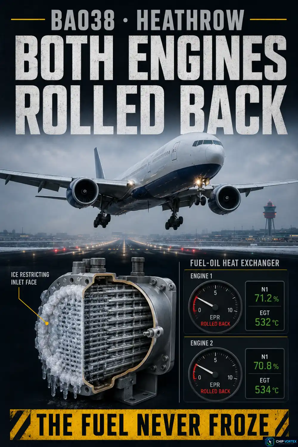
On 17 January 2008, Boeing 777-236ER G-YMMM was on approach to Heathrow from Beijing with 152 people on board. At 720 ft agl the right engine stopped responding to autothrottle demands and rolled back to 1.03 EPR. Seven seconds later the left engine dropped to 1.02 EPR. The aircraft touched down 330 m short of the paved surface of Runway 27L.
The AAIB found that ice had formed from water occurring naturally in the fuel during a long cruise at low fuel flows, then released and restricted flow at the face of the FOHE on both engines. Minimum recorded fuel temperature en route was −34 °C.
Three points students consistently get wrong about this accident:
- The fuel did not freeze. Jet A-1’s freeze point is far lower. The culprit was water in the fuel turning to soft ice.
- The FOHE was certification-compliant. The AAIB found the requirement inadequate, not the part defective.
- Both engines kept running. This was a thrust rollback, not a flameout.
The AAIB identified a “sticky range” of −5 °C to −20 °C, with maximum ice adhesion around −12 °C. Eighteen safety recommendations followed. The NTSB issued an urgent recommendation — addressed to the FAA and EASA, not to Rolls-Royce directly — that they require the Trent 800 FOHE to be redesigned, and FAA airworthiness directives subsequently mandated the modified unit.
Frequently Asked Questions
Why is counter-flow better than parallel flow?▾
Because it holds the temperature difference more constant along the length, giving a higher LMTD and more heat transferred for the same surface area.
How are aircraft heat exchangers inspected?▾
Visually, for debris, dirt, paint overspray and blockage — plate-fin cores cannot be mechanically cleaned, so prevention beats cure. Failures can also be consequential rather than local: FAA AD 2025-23-03, effective 13 January 2026, addresses 757 precooler wear-out combined with latently failed overheat thermal switches, whose unsafe condition is heat damage that could lead to separation of the engine strut from the wing box. It requires strut inspections and thermal switch tests across the 757-200 and -300, plus precooler replacement on the -300 at intervals not exceeding 45,000 precooler flight hours.
What is a compact heat exchanger?▾
One with surface area density above 700 m²/m³ on at least one side for gas-to-fluid duties, or 400 m²/m³ for liquid-to-liquid.
Related reading: the aircraft fuel system and the gas turbine engine.