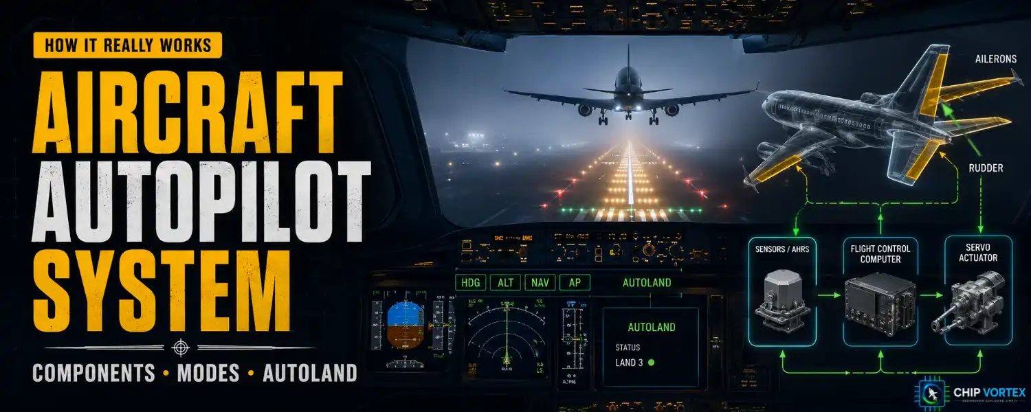
An aircraft autopilot system flies the aeroplane by continuously measuring how far it has drifted from what the crew asked for, and moving the control surfaces to cancel that difference. It does not “know” how to fly. It only knows how to reduce an error to zero — and that single idea explains every component in the system.
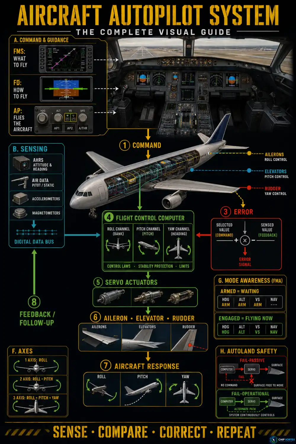
How an Aircraft Autopilot System Works
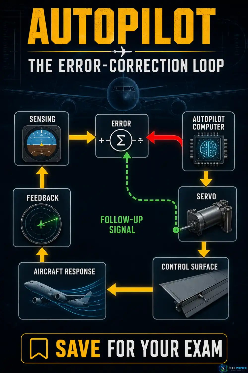
The whole system is a closed loop built on error correction. When the aircraft fails to meet the selected condition — a heading, an altitude, a glideslope — an error exists, and the autopilot corrects it.
The part students miss is the follow-up. As a servo moves a control surface, it generates a signal of opposite polarity that opposes the original command. When the two signals are equal, the servo stops. Without this feedback the system would overcorrect endlessly and the aircraft would oscillate. Follow-up comes in two forms: rate feedback, where the opposing signal grows in magnitude as the surface moves, and displacement feedback, where surface position pickups cancel the error directly.
Aircraft Autopilot System Components
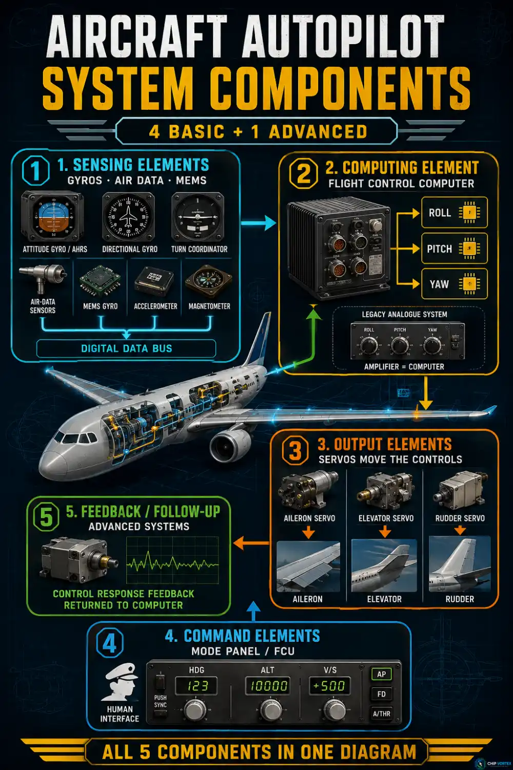
Every airplane autopilot is built from the same elements. The FAA breakdown is four basic components, plus a fifth in advanced systems — get that wording right, because examiners do:
- Sensing elements — attitude and directional gyros, turn coordinator, air data. Modern systems use MEMS gyros, solid-state accelerometers and magnetometers on a digital data bus.
- Computing element — the flight control computer. In older analogue systems the amplifier is the computer; today it is a microprocessor, working in channels that correspond to each axis of control.
- Output elements — the servos that actually move the flight controls.
- Command elements — the mode control panel or FCU. This is the human interface.
- Feedback or follow-up — present in many advanced systems, not all autopilots.
Servo types
Three kinds appear in the handbooks: electric (a motor through reduction gears, or a constantly running motor coupled by magnetic clutches), electropneumatic (an electromagnetic valve assembly driving an output linkage — now largely legacy), and electro-hydraulic (fluid pressure moving the surfaces).
One rule applies to all of them and it is a favourite exam question: a servo must allow completely unimpeded control movement when the autopilot is not operating. Hydraulic servos achieve this by letting fluid flow unrestricted; electric ones declutch.
Do not confuse that with overpowering the autopilot in flight. Garmin’s GFC 500 flight manual supplement is explicit: do not overpower it. The trim runs in the opposing direction, and the resulting out-of-trim force hits you the moment the system disengages. The correct action is always to disconnect.
Single-Axis, Two-Axis and Three-Axis Autopilots
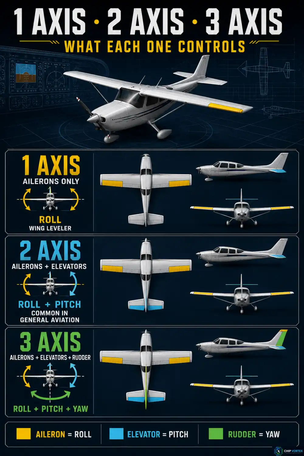
- Single-axis — ailerons only. This is the wing leveler, the simplest autopilot there is, often using the turn coordinator as its sensing element.
- Two-axis — ailerons and elevators, giving roll and pitch. This is the common general aviation fit.
- Three-axis — adds the rudder, giving yaw control as well.
Autopilot Modes: Armed vs Engaged
| Mode | What it does |
|---|---|
| HDG | Steers to a pilot-selected heading |
| NAV | Tracks the course to the active waypoint (lateral only) |
| ALT | Holds the altitude at the moment of engagement |
| ALTS | Armed mode that captures the selected altitude |
| VS | Constant-rate climb or descent in feet per minute |
| FLC / IAS | Climb or descend at a constant airspeed |
| APR | Approach mode — increased sensitivity, and it arms the glideslope |
| LNAV / VNAV | Follows the FMS lateral and vertical flight plan |
Note that on Garmin systems there is no separately selectable LOC mode: pressing APR is what captures the localiser and arms the glideslope together.
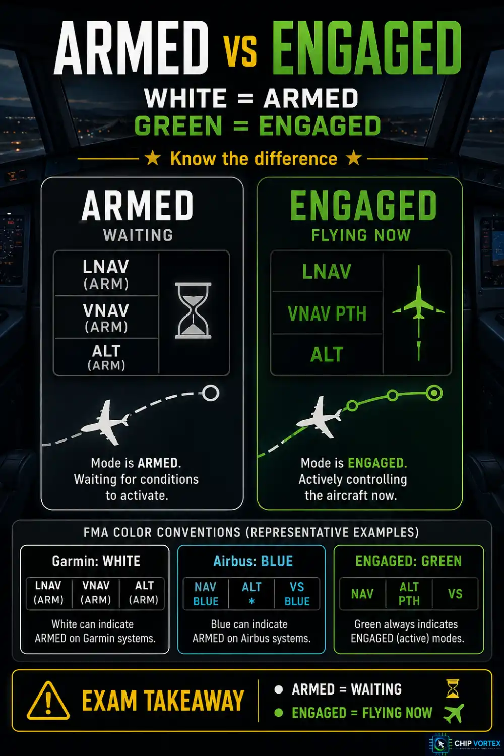
The distinction that causes the most confusion — in exams and in cockpits — is armed versus engaged. An armed mode is waiting for its conditions to be met and is annunciated in white on Garmin displays, blue or magenta on an Airbus FMA. An engaged mode is controlling the aircraft right now, and is annunciated in green on both.
Select an altitude and press a climb mode, and you have a vertical mode engaged and altitude select armed. On reaching the altitude the armed mode captures and becomes engaged. For transport-category aircraft, §25.1329 requires the system to indicate current modes, armed modes, transitions and reversions — because pilots must be able to see this at a glance.
Flight Director, Autopilot and FMS: Who Does What
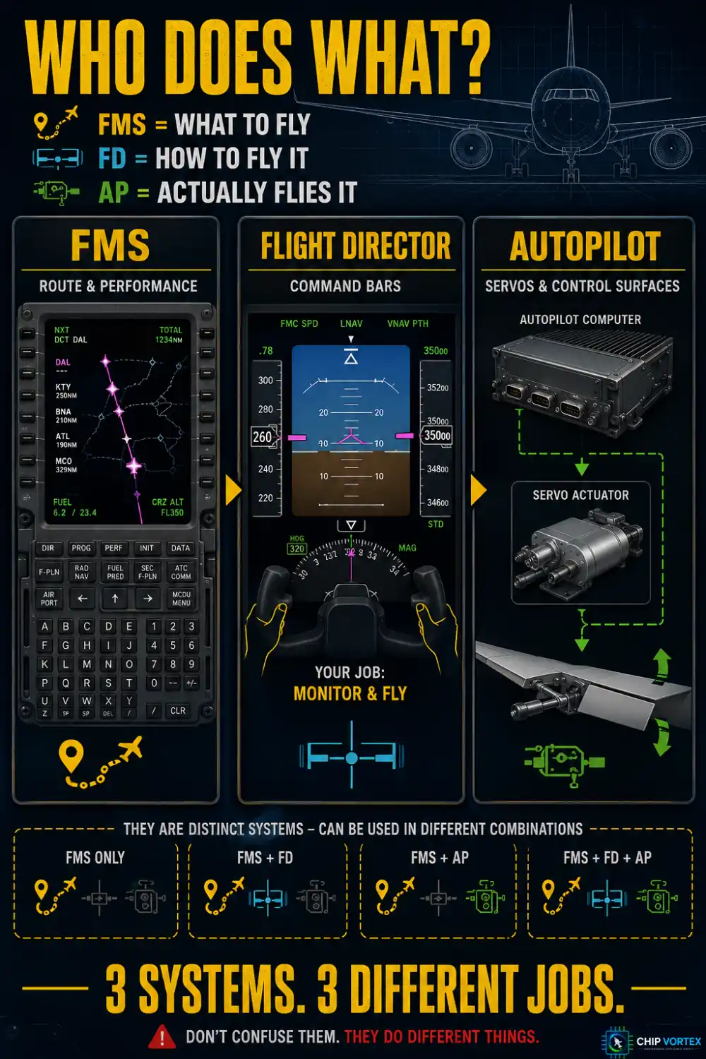
These three are constantly confused. The clean division:
- FMS decides what to fly — the route, the waypoints, the vertical profile.
- Flight director decides how to fly it, and displays the answer as command bars on the attitude indicator.
- Autopilot physically flies it, moving the surfaces through the servos.
You can fly the flight director by hand without engaging the autopilot — a normal technique that simply leaves the workload with the pilot. The reverse is not true on modern systems: engaging the autopilot activates the flight director, and on Garmin installations the FD key is disabled while the autopilot is engaged. The autopilot flies the FD command. Only legacy stand-alone autopilots with no FD fitted at all operate without one.
Autoland and the CAT Categories
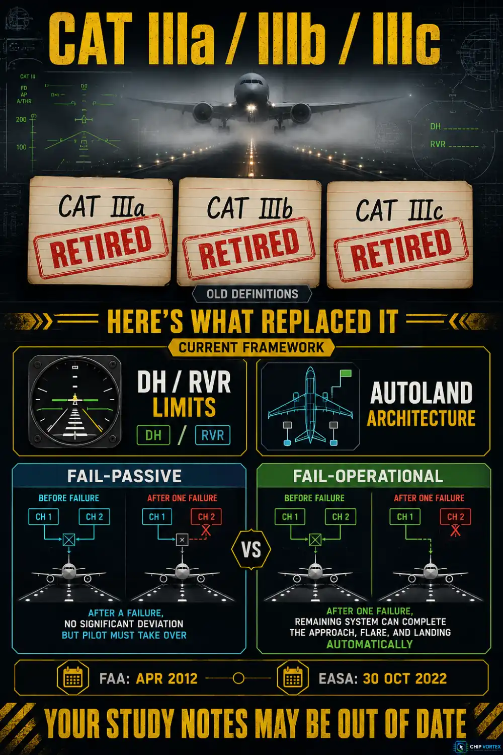
Start with the currency point, because most study material is now wrong here. The CAT IIIa/IIIb/IIIc subdivision has been retired. The FAA removed those definitions from 14 CFR 1.1 by a rule effective 16 April 2012, and EASA followed on 30 October 2022. Current EASA wording is simply “CAT III from a DH lower than 30 m or without DH.”
The legacy ICAO table below is still worth knowing, because it survives in aircraft flight manuals and older textbooks — just know it is legacy:
| Category | Decision height | RVR |
|---|---|---|
| CAT I | Not below 60 m (200 ft) | RVR ≥ 550 m, or visibility ≥ 800 m |
| CAT II | Below 60 m, not below 30 m (100 ft) | Not less than 300 m |
| CAT IIIA | Below 30 m, or no DH | Not less than 175 m |
| CAT IIIB | Below 15 m (50 ft), or no DH | Below 175 m, not less than 50 m |
| CAT IIIC | No DH | No limitation |
Two caveats: CAT IIIC has never been operationally authorised anywhere — there is no ground movement guidance in zero visibility, so it exists on paper only. And these are ICAO metric values; US minima under FAA Order 8400.13E differ, with CAT II down to RVR 1200 rather than 300 m.
The autopilot architecture matters as you go lower:
- Fail-passive — on failure there is no significant out-of-trim condition or deviation of flight path or attitude, but the landing is not completed automatically.
- Fail-operational — after failure of any single component, the approach, flare and touchdown can still be completed by the remaining elements. AC 120-28D accepts dual monitored autopilots, or three autopilots with at least two remaining operative. Airbus annunciates these as CAT 3 SINGLE and CAT 3 DUAL.
Architecture alone does not grant the category, though. The ILS ground facility, critical-area protection, RVR reporting, AFM approval, operator authorisation and crew qualification all have to line up too.
Frequently Asked Questions
How low can the autopilot be used?▾
For Part 121 air carriers, 14 CFR 121.579 sets en route minimum use altitude at whichever is greater of 500 ft, twice the AFM cruise altitude loss, or an altitude specified by the Administrator. On approach the general floor is 50 ft below the DA(H) or MDA. Minimum use altitudes do not apply when an approved automatic landing system mode is being used for landing. Part 135 has its own rule at §135.93; Part 91 operators are bound by the AFM limitations instead.
What happens when the autopilot disconnects?▾
For transport-category aircraft, §25.1329 requires a visual and auditory warning to each pilot, distinct from all other cockpit warnings, and quick-disengagement controls on both control wheels. On Garmin systems an abnormal (automatic) disconnect shows a flashing red AP with a continuous tone, while a normal manual disconnect shows amber with a momentary tone — the colour and the tone together tell you whether you chose it or the system did.
What is mode confusion?▾
Losing track of which mode is actually controlling the aircraft. In the Asiana 214 accident at San Francisco, selecting FLCH SPD and then bringing the thrust levers to idle left the autothrottle in HOLD — a mode that does not control airspeed. The NTSB found that none of the three crew members recalled seeing the FMA change. The probable cause was the crew’s mismanagement of the descent, unintended deactivation of automatic airspeed control, inadequate airspeed monitoring and delayed go-around; autoflight complexity was a contributing factor, not the cause.
Related reading: the aircraft fuel system and the gas turbine engine.