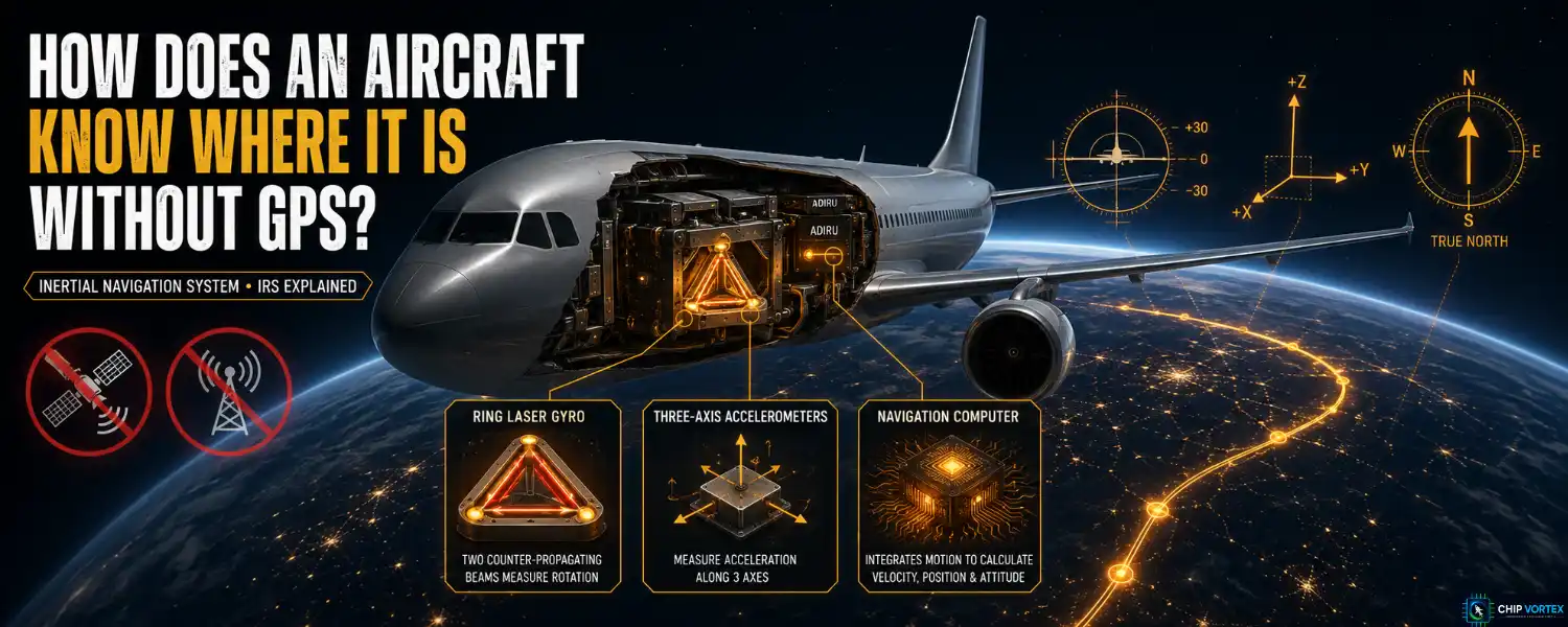
An inertial navigation system knows where an aircraft is without receiving anything from outside it. No satellites, no ground stations, no radio at all. Tell it where it starts, and from then on it works out where it has got to purely by measuring its own acceleration and rotation.
In an era of GPS jamming and spoofing, that self-contained quality has stopped being a historical curiosity and become the reason the system matters.
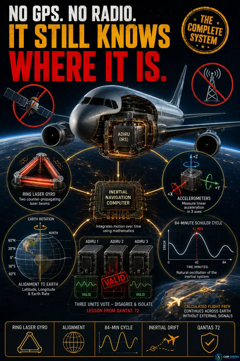
Inertial Navigation System, IRS or IRU?

The terminology confuses students, partly because different manufacturers and reference sources use it inconsistently — SKYbrary, for instance, defines IRS and IRU almost the opposite way round from the usage below. Treat the labels with care and the architecture as the real distinction:
- INS — the older self-contained navigator that computed and displayed position itself.
- IRS (inertial reference system) — the modern equivalent, feeding inertial data to other systems rather than navigating alone.
- IRU (inertial reference unit) — the physical box.
- ADIRU — an IRU with an air data reference built into the same unit.
The INS-to-IRS shift is a real architectural change, not just a rename: a self-contained navigator with its own control unit gave way to a data source feeding an FMS over a digital bus. And the ADIRU distinction is straightforwardly technical.
The split inside an ADIRU is worth memorising. The air data reference (ADR) part supplies airspeed, Mach, angle of attack, temperature and barometric altitude. The inertial reference (IR) part supplies attitude, flight path vector, ground speed and position.
Gimballed vs Strapdown
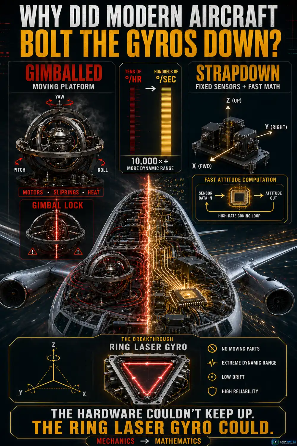
Early systems mounted the sensors on a mechanically stabilised platform held level by gimbals. It worked, but the hardware was punishing — delicate sliprings, motors that generated their own thermal errors, mechanical resonances, and overhauls that meant disassembly.
Gimballed platforms also brought the classic problem of gimbal lock — the loss of a degree of freedom when two gimbal axes align.
Strapdown bolts the sensors rigidly to the airframe and replaces the gimbals with mathematics. The catch was that this demands vastly better sensors: a strapdown gyro must measure hundreds of degrees per second rather than tens of degrees per hour — four to five orders of magnitude more dynamic range — with scale factor accurate to a few parts per million, and the attitude computation running far faster, with a high-rate coning loop underneath the attitude update.
Nothing mechanical could do that. The ring laser gyro could.
The Ring Laser Gyro and the Sagnac Effect
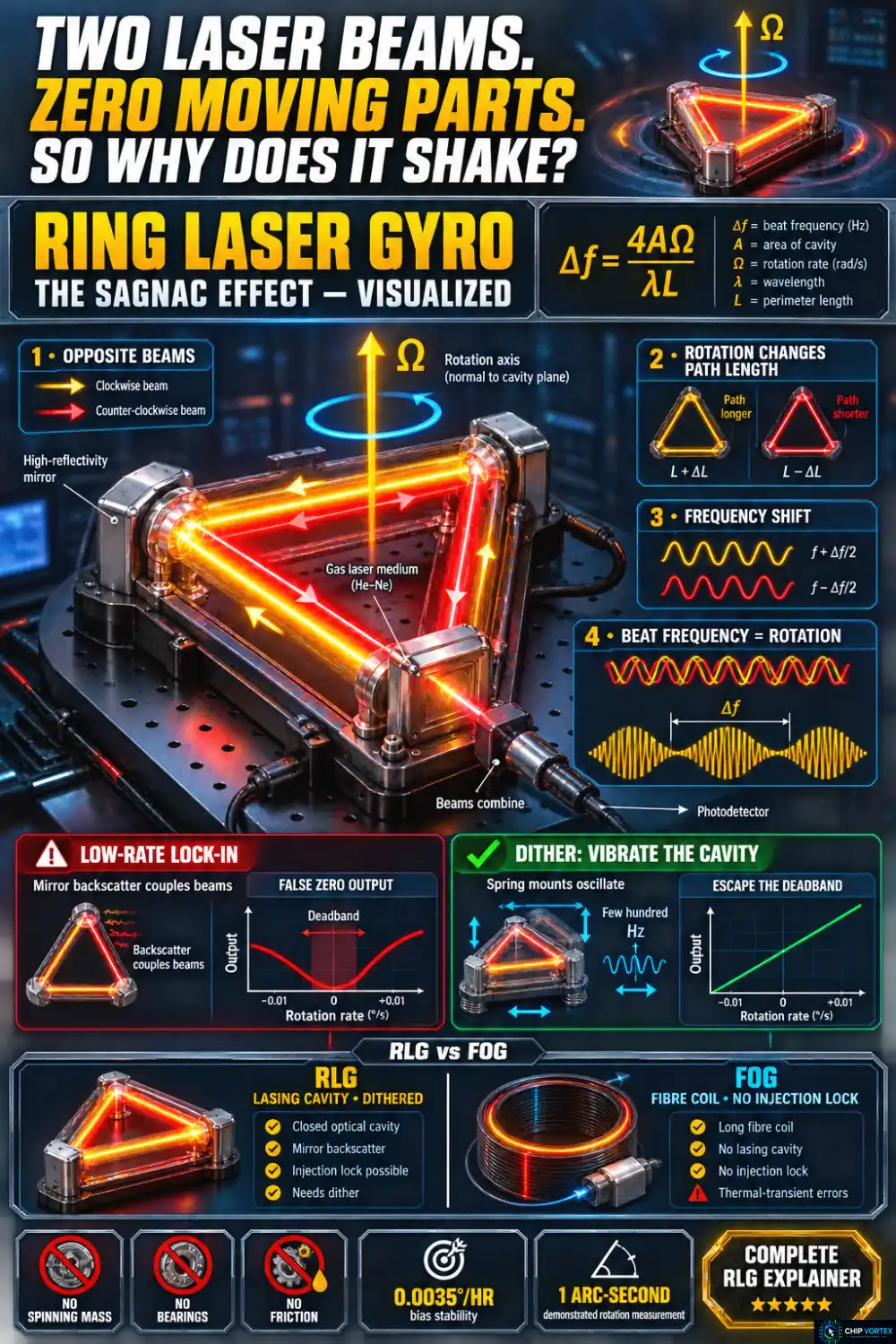
An RLG sends two laser beams around the same closed optical path in opposite directions. Rotate the cavity, and the effective path length grows for one beam and shrinks for the other. Because the cavity is a laser resonator, each beam shifts frequency to keep a whole number of wavelengths in its path. Combine the two beams and you get a beat frequency directly proportional to rotation rate:
Δf = 4AΩ / λL
where A is the area enclosed by the light path, L its perimeter, λ the laser wavelength and Ω the component of rotation rate normal to the plane of the light path. Watch that last qualifier, and watch the units: you will often see the same relation written as 8πAΩ/λL, which is the angular frequency difference in radians per second, not a beat frequency in hertz. The two differ by 2π.
The elegance is in what is absent. There is no spinning mass, no bearing, no friction, and the device does not resist being turned. Honeywell’s GG1320AN — a 1 lb unit about 3.5 inches across — claims a bias stability of 0.0035°/hour and demonstrated capability of measuring one arc-second of rotation.
Lock-in, and why the gyro shakes
RLGs have one awkward flaw. At very low rotation rates the two beams couple through backscatter from tiny mirror imperfections and frequency-lock to each other — producing zero output while the aircraft is genuinely turning. A deadband, right where precision matters most.
The fix is dither: the whole cavity is spring-mounted and mechanically oscillated back and forth about its sensitive axis, typically at a few hundred hertz, so the gyro never dwells inside the deadband long enough to lock. A navigation-grade RLG is, quite literally, vibrating.
Interferometric fibre optic gyroscopes sidestep the problem — there is no lasing cavity, so nothing to injection-lock. Northrop Grumman’s LN-251 uses a non-dithered, low-noise FOG. That is a real structural advantage, though FOGs bring error mechanisms of their own, notably thermal-transient (Shupe) effects.
Why MEMS Cannot Do This Job
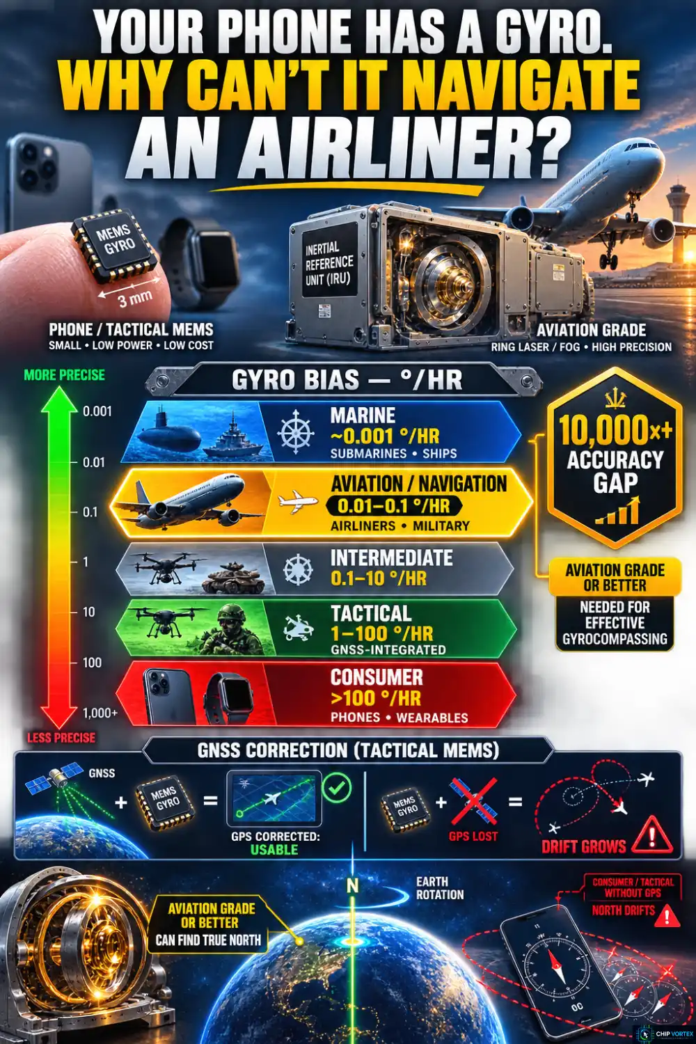
| Grade | Gyro bias | Typical use |
|---|---|---|
| Marine | ~0.001 °/hr | Submarines, ships |
| Aviation / navigation | 0.01–0.1 °/hr | Airliners, military aircraft |
| Intermediate | 0.1–10 °/hr | Between the two |
| Tactical | 1–100 °/hr | Short standalone periods, GNSS-integrated |
| Consumer | >100 °/hr | Phones, fitness trackers |
That is a four-order-of-magnitude spread, and it explains something students often ask: why can’t an airliner use the same MEMS sensors as a phone? Because, as the standard reference on inertial navigation puts it, effective gyrocompassing requires sensors of aviation grade or better. A tactical-grade MEMS unit is perfectly good when GPS is correcting it continuously. It cannot find north by itself.
Alignment: Why the Aircraft Must Stand Still
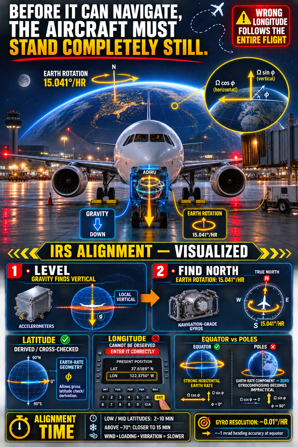
Before flight the system must align, and it must do so stationary. Two things happen.
Levelling uses sensed gravity to find the vertical. Gyrocompassing finds true north by detecting the Earth’s own rotation — 15.041° per hour. That is an extraordinarily small signal, which is why the accuracy hierarchy above matters: to get roughly one milliradian of heading accuracy at the equator, the gyros must resolve about 0.01°/hour.
Two consequences follow.
Alignment gets harder toward the poles. Only the horizontal component of Earth rate is useful for finding north, and that component scales with the cosine of latitude. Approaching the poles it approaches zero, and gyrocompassing becomes impractical.
You must enter present position, and get it right. Crews enter both latitude and longitude, but the two are not equally protected. The system can derive latitude from Earth-rate geometry, so a bad latitude entry gets caught as a gross error. Longitude it cannot observe at all — both gravity and the Earth-rate vector are unchanged by rotation about the spin axis. A wrong longitude propagates straight into every position the system reports for the rest of the flight, with nothing to flag it.
Published alignment times run roughly 2 to 10 minutes at low and middle latitudes, depending on vibration and disturbance. Above about 70° it stretches closer to 15 minutes — the same cosine problem, showing up as time rather than failure. An aircraft being loaded, or standing in wind, aligns more slowly still.
Schuler Tuning and the 84-Minute Oscillation
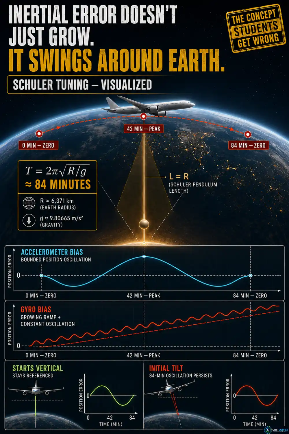
This is the concept students most often get wrong, so here it is precisely.
Maximilian Schuler’s insight was that a pendulum whose period equals 2π√(R/g) — about 84 minutes, where R is the Earth’s radius — stays vertical no matter how its pivot accelerates across the Earth’s surface. An inertial platform behaves as an artificial Schuler pendulum, because a position or tilt error produces a gravity-component error proportional to that error divided by the Earth’s radius, which acts as a restoring term.
The result: inertial errors oscillate rather than diverging. An accelerometer bias produces position error peaking at about 42 minutes — half the period — and returning toward zero at the end of each cycle. Gyro bias behaves differently: it produces a slowly growing ramp with a constant-amplitude oscillation riding on top. The oscillation does not grow; the ramp underneath it does.
One condition is easy to miss. A Schuler pendulum stays vertical under pivot acceleration only if it started vertical. An initial tilt persists as an undamped 84-minute oscillation — which is precisely why alignment quality matters so much.
Schuler tuning is why the error is bounded and wavelike in the short term. It is not why the system is accurate.
So how far does an inertial reference system drift?
Legacy platform systems of the 1970s and early 1980s managed around 2 nautical miles per hour. That number is not folklore — 14 CFR Part 121, Appendix G sets it as a regulatory criterion, requiring circular error no greater than 2 nm/hr on 95% of system flights completed, for flights up to ten hours. What it is not is an ARINC 704A figure, which is where it often gets misattributed.
Modern strapdown units do far better. SKYbrary gives about 0.6 nm/hr, and Northrop Grumman specifies under 0.8 nm/hr CEP free-inertial for the LN-251.
Three Units and a Vote

An A330 carries three ADIRUs of identical design, each providing the same information and operating independently. A single unit going wrong should therefore be harmless.
But “three units” does not automatically mean “majority vote,” and on the A330 angle-of-attack channel it did not. When all three values were valid and consistent, the flight control computers used the average of AOA 1 and AOA 2, with AOA 3 serving as the consistency check. If AOA 1 or 2 deviated significantly from the other two, the computers substituted a memorised value for 1.2 seconds. That is a reasonable design — and it is where the accident happened.
When the Vote Fails: Qantas 72
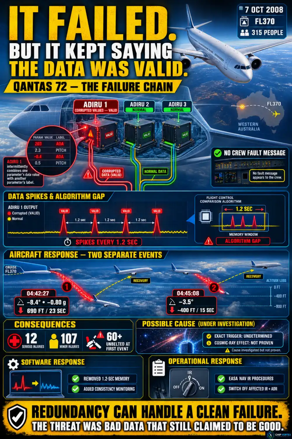
On 7 October 2008, Airbus A330-303 VH-QPA was cruising at FL370 west of Learmonth, Western Australia, with 315 people aboard.
ADIRU 1 — a Northrop Grumman LTN-101, serial number 4167 — began producing intermittent incorrect values on all flight parameters. The ATSB found that its CPU module intermittently “combined the data value from one parameter with the label for another parameter.” The spikes went out to other systems as valid data, with no fault message displayed to the crew. The exact triggering mechanism was never determined; a cosmic-ray single event effect was investigated, but the ATSB found insufficient evidence to determine whether one was involved.
The gap was in the algorithm described above. It could not correctly handle repeated spikes arriving 1.2 seconds apart — the exact interval of its own memorisation period, and exactly what it received.
At 0442:27 the aircraft pitched down 8.4°, reaching −0.80 g. It descended 690 feet over 23 seconds before returning to FL370. At 0445:08 it pitched down again, 3.5°, losing about 400 feet over 15 seconds. Of the 315 occupants, 12 were seriously injured and 107 sustained minor injuries. Among the ATSB’s contributing safety factors: at least 60 passengers were seated without their seat belts fastened at the time of the first pitch-down.
Two separate responses followed, and they are often conflated. Airbus issued interim flight control software that eliminated the 1.2-second memorisation period and added consistency monitoring capable of rejecting a faulty ADR automatically. Separately, EASA Emergency AD 2009-0012-E, effective 19 January 2009, mandated flight crew operational procedures for a NAV IR fault — switching off the affected IR and ADR — not the algorithm redesign.
The lesson is not that redundancy failed. Three units, correctly compared, would have handled a clean failure. What defeated them was a unit that failed while continuing to assert its data was good.
Why Inertial Matters More in 2026
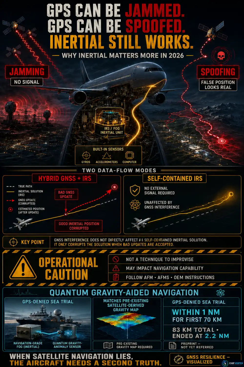
GPS jamming and spoofing have moved this system from background infrastructure to front-line defence. The FAA’s GNSS Interference Resource Guide, updated in March 2026, is blunt about the threat — spoofing “may be so insidious that pilots may be unaware it is occurring” — and it makes a recommendation that turns the usual hierarchy upside down.
Because hybrid systems let GPS update the inertial solution, interference can corrupt a good inertial position. The FAA’s suggestion is therefore to consider aligning the IRS during preflight and disabling GNSS updating before entering a known jamming or spoofing area — since a self-contained inertial system is unaffected by GNSS interference.
Note the qualifier the FAA attaches, because it is the operative sentence: doing this “may impact the navigation capability and must only be performed in accordance with the AFM, AFMS or specific OEM instructions.” It is not a technique to improvise.
The technology is moving too. In August 2026 a quantum gravity-anomaly sensor aiding a navigation-grade FOG inertial system held position error within one nautical mile over the first 70 km of an 83 km sea trial without GPS, ending at 2.2 nm. Two caveats worth carrying: it matched against a pre-existing satellite-derived gravity map, so it is not infrastructure-free, and the result is so far a preprint rather than a refereed publication.
Frequently Asked Questions
Why must present position be entered manually?▾
Because the system can work out latitude from the geometry of Earth’s rotation, but has no means of observing longitude. Get it wrong and nothing catches the error.
Why does a ring laser gyro vibrate?▾
To defeat lock-in. At low rotation rates the two counter-rotating beams frequency-lock and output nothing, so the cavity is deliberately dithered back and forth to keep the gyro out of that deadband.
Does GPS make the inertial navigation system obsolete?▾
The opposite. GPS corrects inertial drift, inertial bridges GPS outages — and when GPS is being jammed or spoofed, the inertial reference system is the one that still works.
Related reading: the aircraft autopilot system, which consumes this data, and aircraft emergency systems.