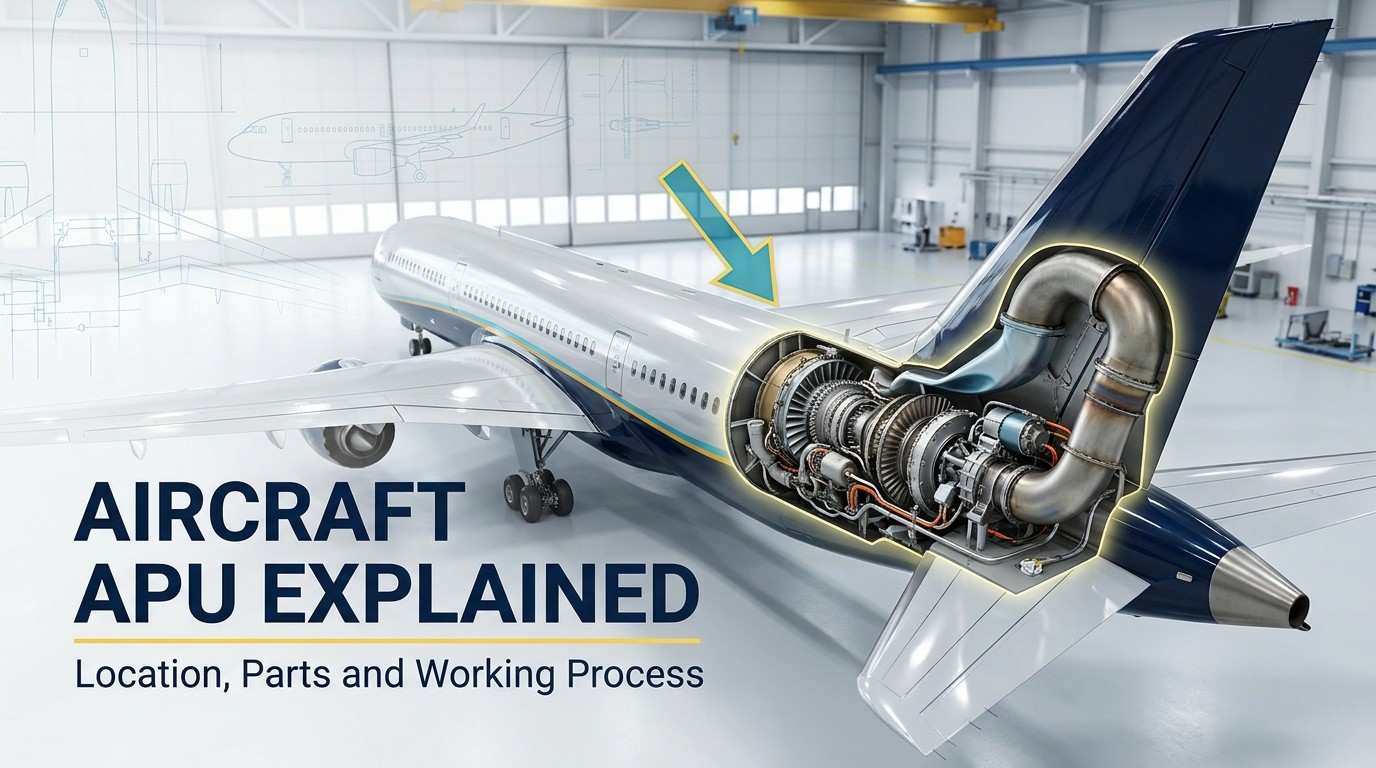
An auxiliary power unit (APU) is a small gas turbine engine mounted in the aircraft’s tail cone that supplies electrical power and pneumatic bleed air independently of the main engines. On the A320 it drives a 90 kVA generator and delivers bleed air for air conditioning and main engine start — on the ground, and within defined limits, in flight.
🔧 Try It Yourself: Interactive Aircraft APU Simulator
Aircraft APU at a Glance
| Question | Simple answer |
|---|---|
| What does APU mean? | Auxiliary Power Unit |
| What type of machine is it? | A small gas-turbine engine |
| Where is it located? | Usually inside the aircraft tail cone |
| Does it produce thrust? | No, it supports aircraft systems |
| What does it supply? | Electrical power and compressed air |
| When is it used? | Mainly on the ground and sometimes in flight |
| Can it start the main engines? | It can provide the power or bleed air needed for starting, depending on the aircraft |
What Does an Aircraft APU Do?
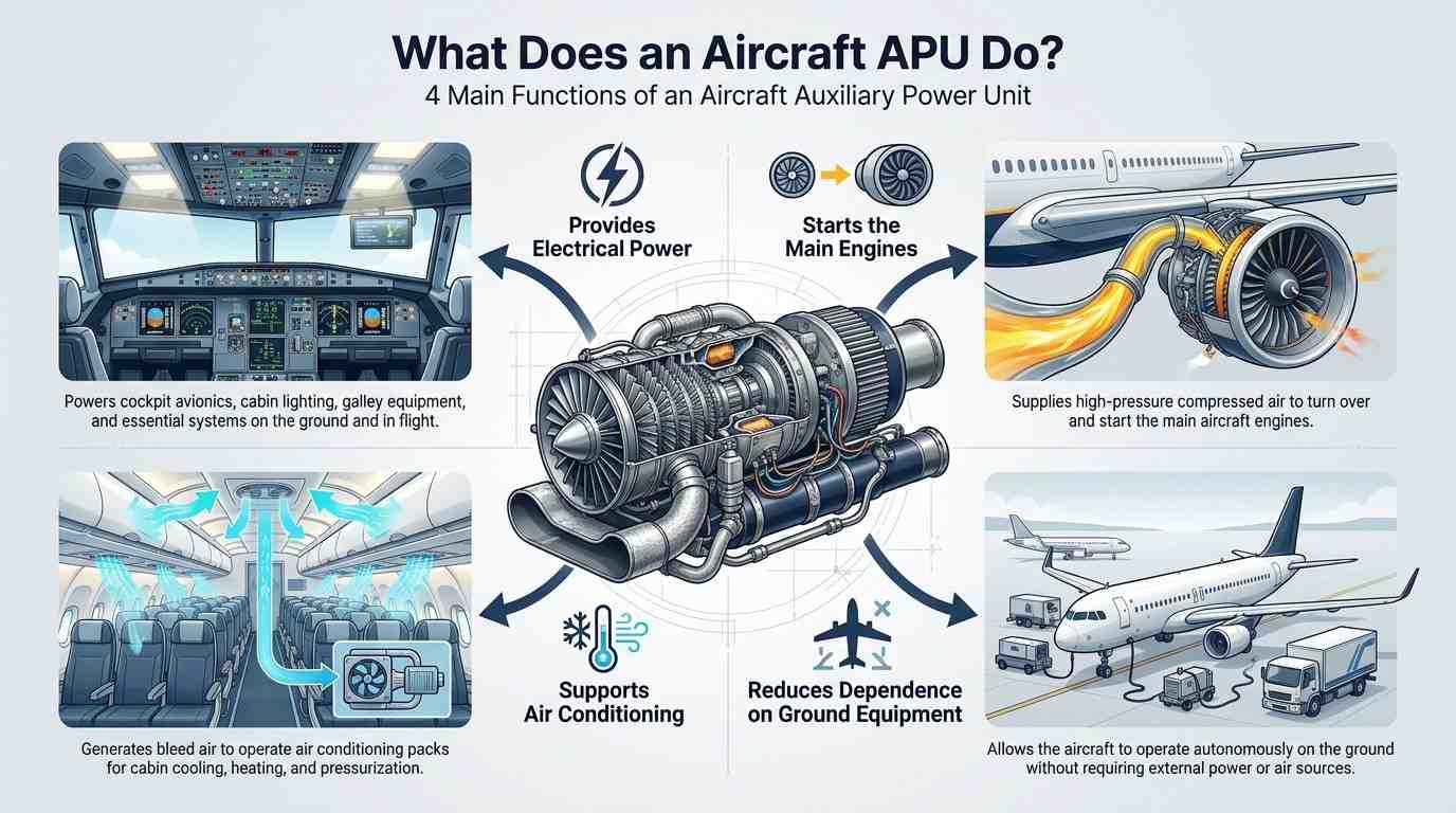
The APU may be smaller than the main engines, but it performs several important jobs.
It Provides Electrical Power
Before the main engines are running, their generators cannot normally power the aircraft. The APU generator can supply electricity to cockpit displays, cabin lights, avionics and other onboard systems.
This allows the flight crew to prepare the aircraft without depending completely on an external ground power unit.
It Supplies Bleed Air
Many conventional airliners use hot, compressed air called bleed air.
The APU can supply this compressed air to the aircraft’s pneumatic system. It may be used to operate the air-conditioning packs and support cabin cooling while the aircraft is parked. Airbus identifies the APU as one of the sources that can supply pressurized air to an aircraft’s air-conditioning system during ground operations. (Airbus Aircraft)
It Helps Start the Main Engines
On many aircraft, the APU provides compressed air to the engine starter.
That air turns the engine’s internal rotating parts. Fuel and ignition are then introduced, allowing the main engine to start and accelerate to a stable operating speed.
Some newer aircraft use more electrical starting systems. For example, Boeing states that normal engine starting on the 787 uses electrical power supplied by the APU. (Boeing)
It Reduces Dependence on Ground Equipment
When the APU is available, an aircraft may not need separate vehicles for electrical power, air conditioning or engine starting.
Boeing’s airport-planning information explains that using the APU can remove the need for electrical, air-start and air-conditioning service vehicles during certain ground operations. (Boeing)
This gives airlines more operating flexibility, especially at airports with limited ground-support equipment.
Where Is the APU Located?
On many commercial airliners, the APU is installed inside the tail cone, at the rear of the fuselage.
For example, Airbus documentation for the A320 family states that the APU is located in the rear fuselage. Air enters through a controlled intake door, while exhaust gases leave through an outlet at the end of the tail cone. (Airbus Aircraft)
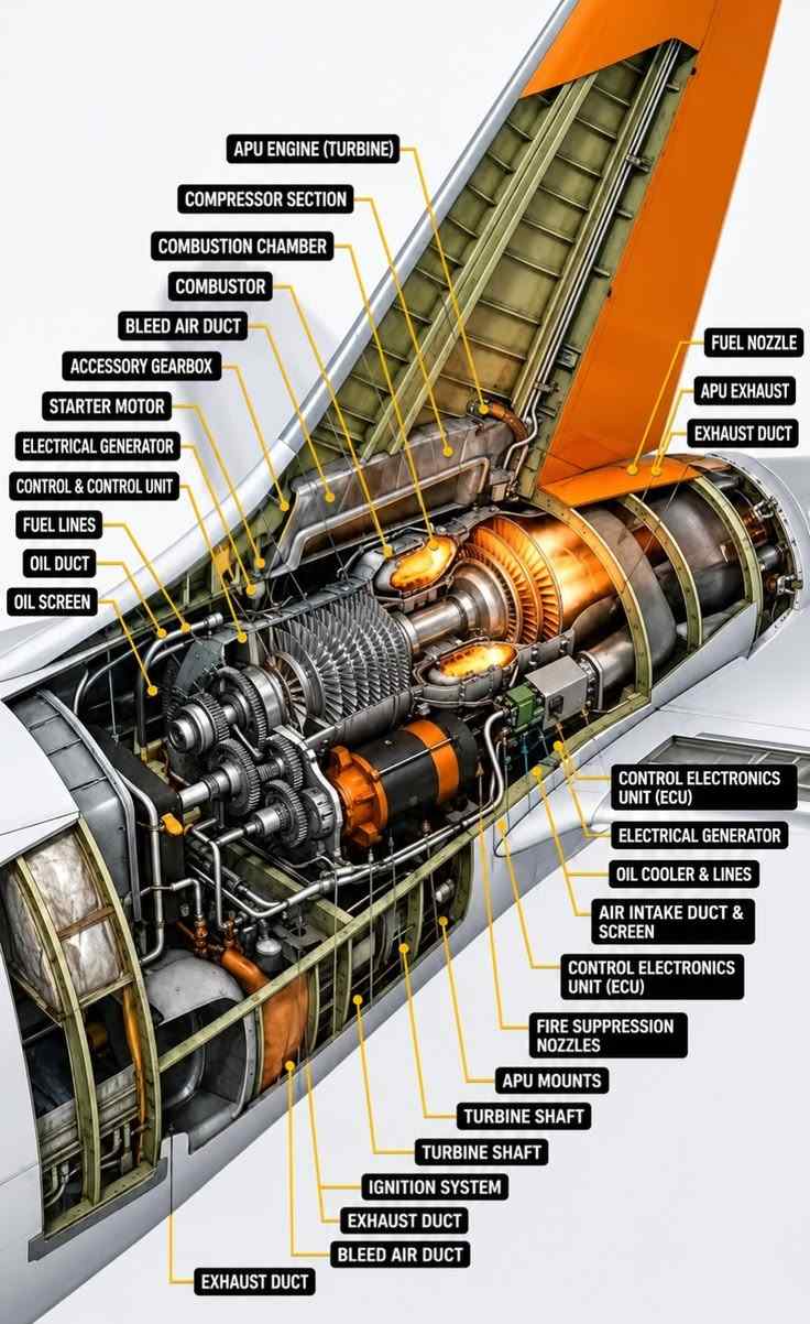
The tail compartment usually includes:
- An APU air intake and intake door
- The gas-turbine unit
- An exhaust duct
- Electrical wiring and control equipment
- Fuel and oil lines
- Bleed-air ducting
- Fire detection and protection equipment
- Maintenance access panels
The exact position and arrangement can change between aircraft and APU models. A simplified diagram is useful for learning, but it should not be treated as an exact maintenance layout for every aircraft.
Image caption: A simplified aircraft APU cutaway showing the compressor, combustion chamber, turbine, generator, gearbox, fuel system and bleed-air components.
Main Components of an Aircraft APU
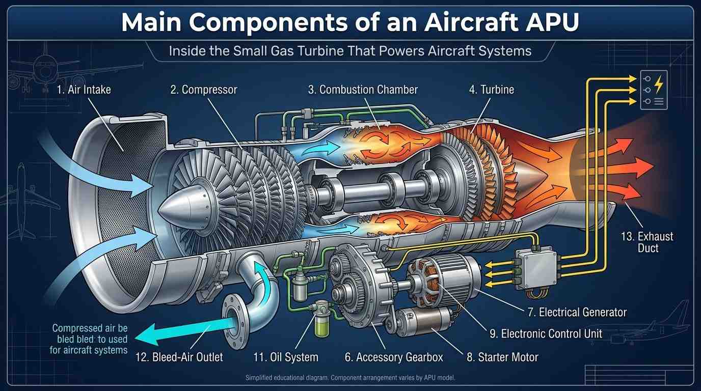
Although APU designs vary, most gas-turbine APUs contain the same basic groups of components.
Air Intake
The air intake allows outside air to enter the APU.
A controlled intake door normally opens when the APU is being started or operated. The air then moves toward the compressor section.
The intake system must provide enough airflow while limiting the entry of unwanted material.
Compressor
The compressor draws air into the APU and raises its pressure.
Rotating compressor blades move the air inward while stationary vanes help control its direction. The compressed air can then be divided between the combustion process and the aircraft’s pneumatic system, depending on the APU design and operating condition.
Some APUs use a separate load compressor to produce pneumatic power, while others use air taken from another compressor stage.
Combustion Chamber
Inside the combustion chamber, fuel is mixed with compressed air.
The igniter starts the combustion process during APU startup. Once stable combustion has been established, the hot expanding gases continue flowing toward the turbine.
The combustion chamber must keep the flame controlled while allowing a continuous flow of high-energy gas.
Turbine
The turbine extracts energy from the hot gases leaving the combustion chamber.
As these gases pass across the turbine blades, they rotate the turbine shaft. This shaft drives the compressor and other connected equipment.
After leaving the turbine, the gases travel through the exhaust system and exit the aircraft.
Turbine Shaft
The shaft connects the rotating sections of the APU.
It transfers mechanical energy from the turbine to the compressor and accessory system. The shaft rotates at high speed and depends on correctly lubricated bearings for smooth operation.
Accessory Gearbox
The accessory gearbox transfers power from the rotating shaft to supporting equipment.
Depending on the APU model, the gearbox may drive components such as:
- The electrical generator
- Fuel pumps
- Oil pumps
- Cooling equipment
- The starting system
- Speed-sensing equipment
The gearbox allows these accessories to operate at the required speeds.
Electrical Generator
Once the APU reaches its operating speed, its generator can supply electrical power to the aircraft.
That electricity may power avionics, lights, pumps, cockpit equipment and other systems before the main engine generators are available.
The aircraft’s electrical system controls how this power is connected and distributed.
Fuel System
The fuel system delivers the correct amount of fuel to the combustion chamber.
Fuel flow must be carefully controlled during starting, acceleration, normal operation and shutdown. Supplying too little or too much fuel can prevent a stable start or create unsafe operating conditions.
Oil System
The oil system lubricates and cools bearings, gears and other moving parts.
It normally includes an oil tank, pump, filters, cooler and associated lines. Proper lubrication reduces friction and helps protect components that rotate at high speeds.
Electronic Control Unit
The Electronic Control Unit, or ECU, manages the APU automatically.
Depending on the aircraft and APU design, it can control:
- Starting and ignition
- Fuel flow
- Acceleration
- Operating speed
- Electrical and pneumatic loading
- Temperature protection
- Automatic shutdown
- Fault recording
This allows the flight crew to operate the APU through a small number of cockpit controls while the control unit manages the detailed sequence.
Bleed-Air System
The bleed-air system carries compressed air from the APU to the aircraft pneumatic system.
This air may be used for:
- Main engine starting
- Operating air-conditioning packs
- Supporting cabin ventilation
- Other approved pneumatic functions
The valves and control system regulate when bleed air is available and how it is delivered.
Exhaust System
After passing through the turbine, the gases leave through the APU exhaust duct.
The outlet can often be seen at the rear of an airliner’s tail cone. The surrounding compartment must be designed to handle heat and protect nearby aircraft structures and systems.
How Does an Aircraft APU Work?
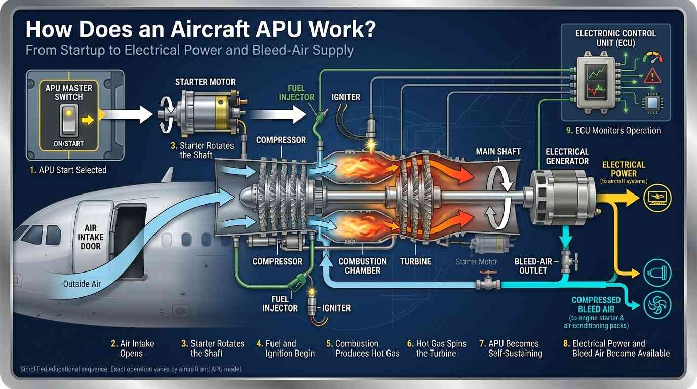
The full operating sequence is automatic on most modern aircraft, but the basic process can be understood in nine steps.
Step 1: The APU Start Is Selected
The crew selects the APU controls from the cockpit.
The control system checks the required conditions and prepares the unit for starting.
Step 2: The Air Intake Opens
The APU intake door opens so outside air can enter.
The exact door position may be controlled automatically according to the APU’s operating condition.
Step 3: The Starter Rotates the Shaft
An electric starter or starter-generator begins rotating the APU shaft.
At this point, the compressor starts moving air through the engine.
Step 4: Fuel and Ignition Are Introduced
Once the correct starting speed is reached, fuel enters the combustion chamber and the igniter creates a spark.
The fuel-air mixture begins to burn.
Step 5: Hot Gas Drives the Turbine
The combustion process creates hot, expanding gas.
This gas flows through the turbine and causes the turbine shaft to rotate faster.
Step 6: The APU Becomes Self-Sustaining
As speed increases, the turbine produces enough energy to drive the compressor without help from the starter.
The starter is then disconnected or changes function, depending on the system design.
Step 7: Electrical Power Becomes Available
After the APU reaches stable operating speed, the generator can be connected to the aircraft electrical network.
The cockpit normally shows an indication that APU electrical power is available.
Step 8: Bleed Air Becomes Available
The APU can then provide compressed air for approved pneumatic uses.
For example, it may supply air to an engine starter or the aircraft’s air-conditioning packs.
Step 9: The Control Unit Monitors Operation
During operation, the ECU monitors speed, temperature, oil condition and other important values.
If it detects a serious problem, the system may limit the APU, close valves or shut it down automatically.
Electrical Power vs. Bleed Air
Many beginners assume that all APU power is the same. In reality, the APU can produce two different forms of useful energy.
| APU output | What it does |
|---|---|
| Electrical power | Operates aircraft electrical and electronic systems |
| Pneumatic power | Provides compressed air for engine starting and air-conditioning packs |
| Mechanical power | Directly drives connected accessories inside some APU systems |
Electrical power travels through cables.
Pneumatic power travels through large, heat-resistant ducts. These ducts carry compressed air rather than electricity.
Understanding this difference makes the full APU system much easier to follow.
Aircraft APU vs. Ground Power Unit
An APU is installed inside the aircraft. A Ground Power Unit, commonly called a GPU, is external equipment connected while the aircraft is parked.
| Aircraft APU | Ground Power Unit |
|---|---|
| Installed onboard | Located outside the aircraft |
| Uses aircraft fuel | Uses an external power source |
| Can produce electrical power | Normally provides electrical power |
| May provide bleed air | Usually does not provide engine-starting air |
| Travels with the aircraft | Stays at the airport |
| Can support some in-flight situations | Used only while the aircraft is on the ground |
A GPU alone may not replace every APU function. When the APU is unavailable, separate conditioned-air or air-start equipment may also be needed.
Is an APU Used During Flight?
An APU is mainly associated with ground operations, but some APUs are approved for in-flight use.
The FAA separates APUs into categories based partly on whether in-flight operation is necessary. Category 1 APUs are used where in-flight auxiliary power is considered necessary, while Category 2 installations do not require the same in-flight role. (FAA)
Depending on the aircraft, an APU may be started during flight to:
- Restore electrical power redundancy
- Support an abnormal electrical condition
- Provide an approved backup power source
- Assist with an engine restart
- Meet a specific operating procedure
This does not mean the APU runs during every flight. Its use depends on the aircraft design, flight conditions and approved procedures.
Why Is the APU Important?
The APU allows an aircraft to operate more independently before the main engines are running.
It helps crews prepare the cockpit, power onboard equipment, cool the cabin and start the engines. It can also reduce the number of ground-support vehicles needed around the aircraft.
For passengers, the APU helps keep the cabin comfortable before departure.
For flight crews and ground teams, it provides a reliable onboard source of supporting power.
For maintenance technicians, it is a compact system that combines gas-turbine technology with electrical, pneumatic, fuel, oil, fire-protection and electronic-control systems.
📖 Beyond the Diagram How It Looks in the Real World
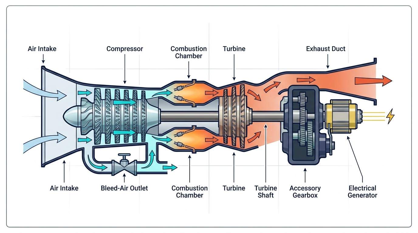
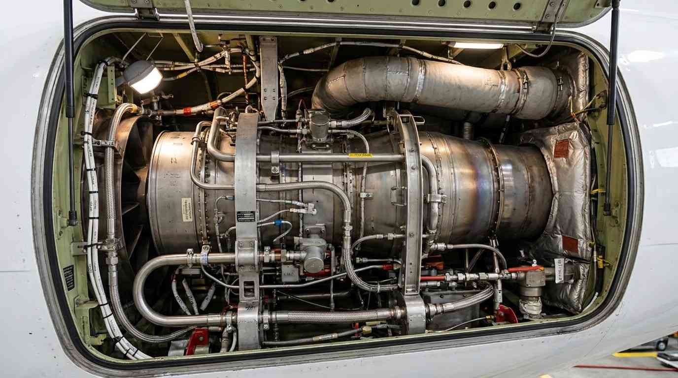
A clean cutaway shows the APU as a compact gas-turbine unit with a few clearly separated parts: air intake, compressor, combustion chamber, turbine, gearbox, generator and bleed-air outlet.
Inside the aircraft tail cone, the APU sits in a tight compartment surrounded by intake ducting, exhaust structure, wiring harnesses, fuel and oil lines, sensors, fire-protection components, brackets, clamps and access limitations.
The diagram explains how the APU works. The real installation shows where everything actually sits and what technicians must work around. For inspection, troubleshooting and maintenance, both views matter.
Frequently Asked Questions
Is an APU a jet engine?▾
An APU is a gas-turbine engine, but it is not a propulsion engine.
It uses compression, combustion and turbine rotation like a jet engine. However, its main purpose is to produce supporting power rather than forward thrust. FAA standards specifically separate APUs from gas-turbine engines intended for aircraft propulsion. (FAA)
Does every aircraft have an APU?▾
No.
APUs are common on commercial airliners and larger aircraft, but many smaller aircraft do not need one. They may use batteries, engine-driven generators or external ground equipment instead.
Can an aircraft operate with an inoperative APU?▾
In many cases, an aircraft can operate without a working APU, but the exact conditions depend on the aircraft, airport facilities and approved operator procedures.
External electrical power, conditioned air or pneumatic starting equipment may be required. Boeing documentation for the 787, for example, describes alternative engine-starting support when the APU is unavailable. (Boeing)
Does the APU run during the entire flight?▾
Usually not.
It is commonly shut down after the main engines and their generators are operating. It may be used again during flight when required by an approved procedure or system condition.
Does the APU provide air conditioning directly?▾
The APU does not normally create cold cabin air by itself.
It supplies electrical power or compressed bleed air to the systems that operate the aircraft’s air-conditioning packs.
Why is the APU exhaust at the back of the aircraft?▾
On aircraft with a tail-cone APU, placing the exhaust outlet at the rear provides a direct path for hot exhaust gases to leave the compartment.
The exact design depends on the aircraft model.
Final Thoughts
The Aircraft Auxiliary Power Unit is a small engine with a major responsibility.
Long before the main engines begin producing power, the APU can supply electricity, support cabin air conditioning and help start the engines. Inside its compact casing, the compressor, combustion chamber, turbine, generator, gearbox and control system work together as one complete power unit.
The next time you board an aircraft while its main engines are still silent, listen carefully. The low humming sound from the rear may be the APU already working behind the scenes.
Technical References
The technical explanation is based on official FAA material and aircraft manufacturer information covering APU classification, non-propulsive power, electrical generation, pneumatic air, engine starting and tail-cone installation. (FAA).